Hitachi Inverters

Hitachi inverters can be utilized for an array of industrial applications. Hitachi inverters are equipped with several advanced features, and deliver unprecedented performance, reliability, and flexibility. Hitachi inverters are a result of a high degree of commonality between each model and the user-friendly configuration software, making them easy to install, program, and maintain. Hitachi inverters are manufactured to provide an economical solution for industry’s most challenging applications.

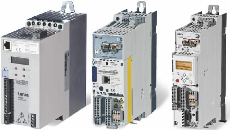
NE-S1 Hitachi Inverters

NE-S1 Hitachi inverters are simple to use for speed control solutions are are available in the popular horsepower range of 1/2 hp through 5 hp. NE-S1 inverters have an ultra-compact design, and are pre-configured for out of the box integration in most applications to suit the needs of both OEMs and System Integrators. NE-S1 inverters reduce installation space by attaching FFM, so ventilation is exhausted to the front. This allows the inverter to save panel space and cost to the overall installation. NE-S1 inverters improves capacitor life by attaching FFM to applicable model. The expected life of the aluminum electrolytic capacitors is approximately doubled, adding longevity to NE-S1 inverters.

NE-S1 inverters are seen in many applications such as:

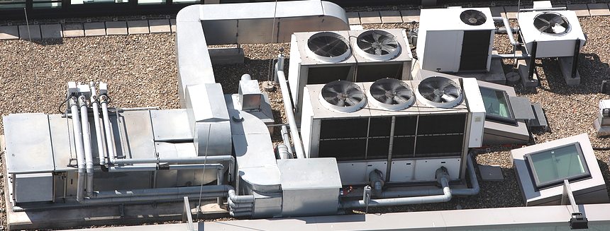
  • Air conditioning systems
  • Fans and blowers
  • Clean rooms
  • Pumps
  • Water and wastewater pump systems
  • Tank-less water supply and drainage systems
  • Food Processing Machines
  • Slicers
  • Mixers
  • Confectionery machines
  • Fruit Sorters
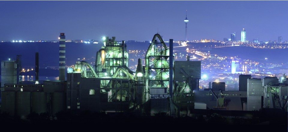
  • Machine Retrofits for all industries


SJ700D Hitachi Inverters

SJ700D Hitachi inverters outperform on performance, capabilities and functions of its predecessor, the Hitachi SJ700B Series. SJ700D inverters come with improved sensorless vector (SLV) control algorithm, which allows the SJ700D Series to develop 150% torque at 0.5 Hz, ideal for a wide range of applications. Another key upgrade in the SJ700D Series is the addition of Hitachi’s EzSQ (Easy Sequence) built-in programming function, which provides the functionality of a PLC built into the inverter. SJ700D inverters offer built in programming functions. Sequence operations are used by downloading programs created with Hitachi’s EzSQ software and then transferred to the Hitachi inverters. Operation of SJ700D inverters can be tailored to meet changing process requirements and SJ700D inverters can replace separate PLC’s in some cases to simplify or eliminate external hardware, which reduces cost and increases performance. SJ700D Hitachi inverters through 150kW have a built-in EMC filter to reduce electromagnetic noise, cost and space. SJ700D inverters have a lifetime warning function to allow preventive maintenance before a failure occurs.

WJ200 Hitachi Inverters

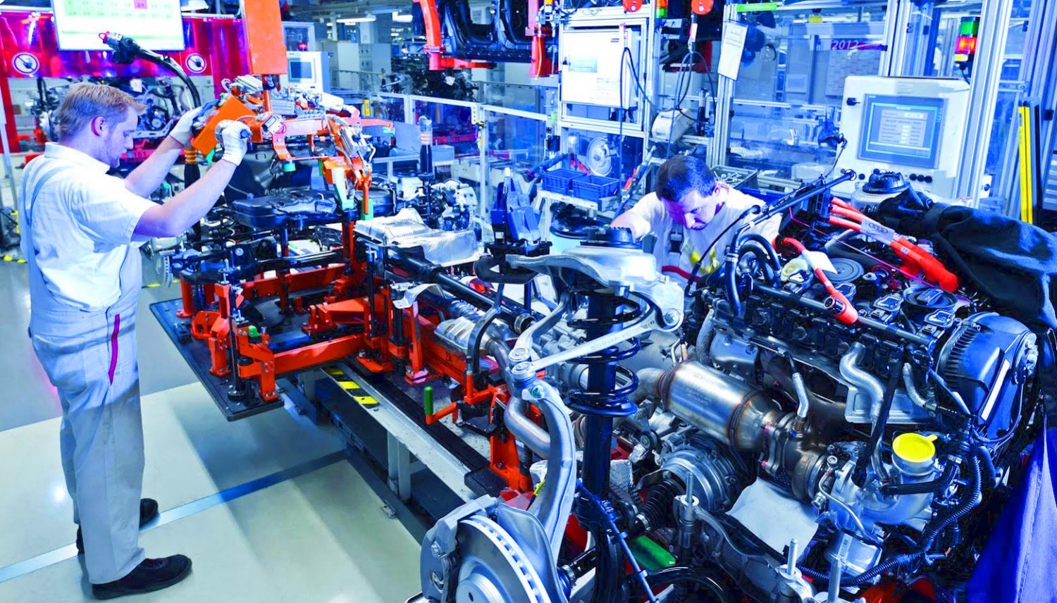
WJ200 Hitachi inverters are designed for excellent performance and user friendliness. The WJ200 series is available in power ranges from 100-200VAC and single phase input to three phase output. The WJ200 series has an integrated auto-tuning function for easy sensorless vector control. Sensorless vector control allows for high starting torque of 200% or greater and is suitable for a variety of applications. Simplified auto-tuning procedure for WJ200 inverters allow for ease of setup and operation via standard integral keypad, optional enhanced keypad or via PC software. There’s also a built-in dynamic braking transistor in all WJ200 inverter models. WJ200 inverters are capable of driving permanent magnet as well as standard induction motors. WJ200 inverters are seen in a wide range of industrial manufacturing applications.

To learn more about Hitachi inverters or for Hitachi Inverter repair and replacement quotes, contact Precision Electric.

Cutler Hammer VFD

Cutler Hammer VFD drives can reduceenergy consumption from 10 to 50 percent by adjusting the speed of its corresponding electric motor to its needed output. Cutler Hammer VFD drivesallows for steady speed error, fast torque rise time, high immunity to resonance vibrations and high starting torque and current. Cutler Hammer VFD drives can be customized to fitmultiple motor drive systems and high-speed applications. Cutler Hammer VFD drivescan be designed specifically for high-performance applications withhigh processing power, and the ability to use information from an encoder or resolver to provide precise motor feedback control. Cutler Hammer VFD drives also offer a uniquemicroprocessor to provide high dynamic performance for applications where precisemotor handling and reliability are required.

The Cutler Hammer DG1 General-Purpose drives are part of the Eaton next-generation PowerXL series of variable frequency drives specifically engineered for todays more demanding commercial and industrial applications.Cutler Hammer DG1 General-Purpose drives offeran industry-leading energy efficiency algorithm, high short-circuit current rating and robust design, safety and reliability. Cutler Hammer LCX9000 drives are liquid-cooled products that utilize potable water or a water-glycol mixture as a cooling medium. The LCX9000 has a compact size and low heat transfer rates to allow the enclosure size to be greatly reduced, which is especially beneficial in UL Type 4X applications.

Cutler Hammer PowerXL Enclosed Drivesare a next generation enclosed drive platform that packages Cutler Hammer’sPowerXL DG1 and SVX drive families in a fast and reliable design solution. Cutler Hammer CFX9000 Clean Power Drivesuse tuned passive filters to significantly reduce line harmonics at the drive input terminals. These drives are an excellent choice for small and midsize applications where harmonics are a concern. Cutler Hammer VFDCPX9000 Clean Power Drivesare used for water, waste water, HVAC, industrial and process industries where harmonics are present. They offer one of the purest sinusoidal waveforms available.

Cutler HammerMVX9000 Micro Drivesare sensorless vector variable frequency drives are designed to provide adjustable speed control of three-phase motors. EatonSLX9000 General Purposedrives are compact, yet powerful drive is based on the more robust SVX9000. It is designed to be the next generation of drives specifically engineered for modern commercial and light industrial applications.

Obsolete Cutler Hammer VFD Drives

The HVX series of Cutler Hammer VFD drives are obsolete. The HVX series of Cutler Hammer VFD drives are currently replaced by Cutler Hammer VFDEaton H-MAX drives.The HMAX series of HVAC frequency drives are designed to the HVAC market for fan, pump, and fluid control applications. The patented energy savings algorithm, high short-circuit current rating and intuitive user interface provide customers an energy efficient, safe, and easy to use solution for adjustable frequency drive needs.The H-MAX drive supports the increasing demand for energy savings in buildings, systems and facilities. Built in capabilities and unique features provide a competitive solution that can add value to any end user.

The MVX9000 series of Cutler Hammer VFD drives are obsolete and replaced by Cutler Hammer VFDEaton M-MAX drives.The M-Max Drive is a compact micro drive with a broad power range. The M-Max series of Cutler Hammer VFD HVAC frequency drives feature board coating, unique mounting characteristics, simple programming, and 50C Rating to makethe M-Max perfectly suited for machinery applications in many industries. Typical applications for the M-Max drives include Food and Beverage, HVAC, Packaging, Pumping, Textile, OEM, and more.

For Cutler Hammer VFD Repair and Replacement quotes, Contact Precision Electric.

VFD Device

A VFD device is also known as Variable Frequency Drive, variable speed drive, adjustable speed drive, electronic motor controller, or an inverter.

A VFD device is a solid state electric motor control system designed to control the speed of an electric motor. VFD devicesoperate as load controls within electric motor applications; and a VFD devicecan reduce energy costsup to 50% by speed reduction on electric motorswhere the full speed of the electric motor is not needed.VFD devices are used in AC servo systems, air compressors, conveyor systems, lathes, mills, plastic extrusion, slitter lines, food processing, waste water treatment systems, submersible pumps, HVAC fans, blowers, and many more electric motor applications.

Many manufacturers will apply a VFD device to rotating equipment to reduce amperage spikes upon start up of large electric motors.Choosing the right VFD device for an application can aid rotating equipment by providing less wear on the electric motors where applied.Adjusting the acceleration and deceleration time of electric motors can extend the lifespan of an electric motor. VFD devicesprovide the ability to control the frequency of starting and stopping of an AC electric motor.This ability allowsan AC electric motor to only operate when needed for the equipment its rotating, and electric motors have a longer lifespan if they are only running when needed.

Approximately one third of electrical energy in the world is supplied by electric motors in fixed-speed centrifugal pump, fan, and air compressor applications. These fixed-speed applications don’t usually needthe full load speed of the electric motor theyre operating. By installing a VFD device to these applications, electric motor speeds are reduced, and power costs can be reduced by 50% or more. Technology has allowed cost and physical size reduction of VFD devices, and has improved performance through advances in semiconductor switching devices, simulation, control techniques, control hardware and software.

A properly applied VFD device and electric motor will significantly reduce energycosts for manufacturers. This is particularly true for variable torque loads such as fans, blowers, and pumps.Blowers are often used with dampers to control air flow; These dampers may operate either manually or automatically. When dampers are closed, 50% of the electric motor current will drop to approximately 60% of full load nameplate current. By utilizing a VFD devicein blower applications, the current draw of the motor will be reduced 30% for every 10% drop in speed; The same electric motor operating froma VFD device at 50% speed, will draw approximately 20% of the full load current.

To learn more about a VFD device orfor VFD device repair and replacement quotes, contact Precision Electric, Inc.

How Do VFDs Work

How Do VFDs Work?A variable frequency drive is also known as a VFD, variable speed drive, adjustable speed drive, electronic motor controller, or an inverter. How do VFDs work? Every VFD is unique with its own component characteristics so how each VFD works is dependent upon components within the VFD. Most VFDs integrate a solid state electronics controller consisting of a bridge rectifier, a converter, and an inverter module.

Voltage-source inverter drives are the most common type of VFDs. These drives convert AC line input to AC inverter output.There are some applications that use common DC bus and solar applications. These type of drives are configured as DC to AC drives. The bridge rectifier converter for volts per hertz drives is configured for 3 phase AC electric motors. Volts per hertz drives usea capacitor to smooth out the converter DC output ripple and provides a solid input to the inverter.

This filtered DC voltage is converted to AC voltage output using the inverter’s active switching elements. VSI drives provide higher power factor and lower harmonic distortion (noise) than phase controlled current source inverters and load commutated inverters drives. The drive controller can also be configured as a phase converter having single-phase converter input and three-phase inverter output.Controller advances have allowed increased voltage and current ratings and switching frequency of solid-state power devices over the past 50 years. VFDs were first introduced in 1983, and the insulated gate bipolar transistor has in the past 20 years become the standard for VFDs as an inverter switching device.

In variable-torque applications using Volts per Hertz (V/Hz) drive control, AC motor specifications require that the voltage magnitude of the inverter’s output to the motor be adjusted to match the required load torque in a corresponding V/Hz relationship. For 460 VAC, 60 Hertz electric motors, this V/Hz relationship would be 460/60 = 7.67 V/Hz. While acceptable in a wide range of different applications, V/Hz control is sub-optimal in high performance applications. High performance applications requiring low speed control, demanding high torque, dynamic speed regulation, positioning, and reversing load demands, there are open loop VFDs and closed loop VFDs would be desired over V/Hz VFDs.

How Do VFDs Work In Manufacturing

Many manufacturers will apply variable frequency drivesto rotating equipment to reduce amperage spikes upon start up of large electric motors. Choosing the right VFD for an application will benefit rotating equipment by providing less wear on the electric motors where applied. Adjusting the acceleration and deceleration time of electric motors can extend the lifespan of an electric motor. Variable frequency drives provide the ability to control the frequency of starting and stopping of an AC electric motor. This ability allows an AC electric motor to only operate when needed for the equipment its rotating, and electric motors have a longer lifespan if they are only running when they need to be.

Approximately one third of the worlds electrical energy is supplied by electric motors in fixed-speed centrifugal pump, fan, and air compressor applications. These fixed-speed applications hardly ever require the full load speed (RPM) of the electric motor in which theyre operating. By installing a VFD to these applications, electric motor speeds are reduced, and power costs can be reduced by 50% or more. Technology has allowed cost and physical size reduction of variable frequency drives, and has improved performance through advances in semiconductor switching devices, simulation, control techniques, and control hardware and software.

How Do VFDs Work For Power Savings

The majority of variable frequency drives in the market today contain electronic circuitry that converts 60 Hertz Line power into direct current. The variable frequency drive converts this line power into a pulsed output voltage that duplicates varying alternating current to a desired frequency (speed). A properly applied VFD when paired with the correct electric motor will significantly reduce operating costs for manufacturers. This is particularly true for variable torque loads such as fans, blowers, and pumps. Blowers are often used with dampers to control air flow; these dampers may operate either manually or automatically. When dampers are closed, 50% of the electric motor current will drop to approximately 60% of full load nameplate current. By utilizing variable frequency drives in blower applications, the current draw of the motor will be reduced 30% for every 10% drop in speed. The same electric motor operating from an AC variable frequency drive at 50% speed, will draw approximately 20% of the full load current.

Are you still asking yourself, How Do VFDs Work? Please watch our YouTube Video,or contact us via email. For VFD repair and replacement quotes, contact Precision Electric, Inc.

Eaton Overcurrent Protection

Eaton overcurrent protection and Eaton current control for the Eaton9000X drive is based on motor current measurement in all three phases. In the Frame 9/ Chassis 61 Eaton drives, the current sensors are built into the IGBT SKIP modules, and the current signals are combined and fed into a 14-bit A/D converter on the lower ASIC board. The ASIC board sends the current levels to the control board via a fiber optic serial link. In the smaller Eaton Frame 8 / Chassis 5 drives (and below), the measured current signal is fed directly to the control board. The EatonSVX9000drive has a 10-bit A/D converter and the EatonSPX9000drive has a 14-bit A/D converter.

Eaton overcurrent protection for the 9000X air-cooled frequency converter ratings are based on a High Overload (IH) capability. This means the drive can provide 150% rated output current for 1 minute if the drive was operating at rated output current (IH) for at least 9 minutes. To get continued 150% overcurrent capability, the average current over the duty cycle cannot exceed the rated output current. The maximum drive output current (IS) for starting produces approximately 200% rated motor torque but because the currents are vector sums, IS is less than 200% IH. The drive can deliver IS for 2 seconds every 20 seconds. The drive current limit can be set to 200% (2 x IH) to deliver IH but to reduce the chance of an overcurrent or IGBT over temperature trip, it is better to set the current limit to 150% (1.5 x IH) or less.

The actual drive output current available to the motor is dependent on ambient temperature at the intake to the drive, restrictions in airflow to the drive, and the drive frame size. Drive frames FR4FR9 can deliver rated current (IH) at 50C. Drive frames FR10 and above can deliver rated current (IH) at 40C except for the highest ratings of a drive frame, which may be limited to 35C. The Low Overload (IL ) rating is typically used for variable torque loads where an overload is not necessary even though a 1 (out of 10) minute overload of 110% is allowed. All drive frames are limited to 40C or less for the IL rating. The rated currents of each frame depend on a reduction of switching frequency when unit temperature reaches the warning level.

Eaton overcurrent protection in the liquid-cooled drive has a Thermal maximum continuous rms current (Ith). Use this value for continuous or any overload requirements of the process. The liquid-cooled drive does not have a 1-minute overload current rating. The thermal current rating is dependent on proper coolant flow to each module and a module coolant inlet temperature of 30C. Current limit (software-function) The drive will attempt to limit drive output current to the current limit setting by overriding and lowering the frequency reference until current is within the current limit setting. If unit temperature nears the warning level, the drive will reduce the output frequency in an attempt to bring drive output current down to a continuous current that is approximately the Low Overload (IL ) current rating. The control will not allow any further overcurrent conditions until the average current over the duty cycle is less than the drives current rating. The liquid-cooled drive control will attempt to limit the output current to the current limit setting up to the drives thermal rating. The application should be designed to avoid using the current limiter for control.

The safest way to operate an Eatondrive is to keep the drive output current within ratings with appropriate ramp times or a controlled reference to the drive. If the drive software cannot prevent output current from exceeding 200% IH, a current cutter stops firing the IGBTs when the measured instantaneous value of the current exceeds 360% IH to reduce current quickly before an overcurrent trip occurs. They are re-fired on the next top of the triangle wave. The current cutter is active on select units FR8/CH5 and smaller. If the measured instantaneous value of current exceeds the trip limit value (260400% depending on drive size), all IGBTs are switched off and the drive displays an F1, overcurrent trip. The drive is protected from a short circuit at the motor if the motor leads are greater than 16 feet (5m) in length.

Only trained and experienced electricians should work withEaton overcurrent protection. For more safety information about Eaton overcurrent protection, visit the Eaton Website. For Eaton drive repair and Eaton drive replacement quotes, contact Precision Electric.

Eaton Low Voltage Drives

Eaton low voltage drives (also known as variable frequency drives) adjust an electric motor’s speed to closely match output requirements, resulting in a typical energy savings of 10 to 50 percent.

Eaton’s SVX9000 adjustable frequency drive offers sensorless vector control technology coupled with an adaptive motor model and sophisticated ASIC circuit features. This technology allows for steady speed error, fast torque rise time, high immunity to resonance vibrations and high starting torque and current. The SVX9000 is suitable for multiple motor drive systems and high-speed applications.EatonSPX9000 drives are designed specifically for high-performance applications. Eaton SPX9000 drives feature high processing power and the ability to use information from an encoder or a resolver to provide precise motor control. In addition, a fast microprocessor provides high dynamic performance for applications where good motor handling and reliability are required.

The Eaton DG1 General-Purpose drives are part of the Eaton next-generation PowerXL series of adjustable frequency drives specifically engineered for todays more demanding commercial and industrial applications. With an industry-leading energy efficiency algorithm, high short-circuit current rating and robust design, the Eaton DG1 General-Purpose drives offer increased efficiency, safety and reliability.Eaton’s LCX9000 drives are liquid-cooled products that utilize potable water or a water-glycol mixture as a cooling medium. Their compact size and low heat transfer rates allow the enclosure size to be greatly reduced, which is especially beneficial in UL Type 4X applications.

Eaton offers industry-leading technology for applications where harmonics are a concern. Eaton’s clean power drives significantly reduce line harmonics at the drive input terminals and provide some of the purest sinusoidal waveforms available.EatonPowerXL Enclosed Drivesis a next generation enclosed drive platform that packages Eatons PowerXL DG1 and SVX drive families in a versatile, fast, and reliable design solution.

EatonCFX9000 Clean Power Drivesuse tuned passive filters to significantly reduce line harmonics at the drive input terminals. These drives are an excellent choice for small and midsize applications where harmonics are a concern. EatonCPX9000 Clean Power Drivesare the clear choice for applications in the water, wastewater, HVAC, industrial and process industries where harmonics are a concern. They offer one of the purest sinusoidal waveforms available.

EatonCP to CPX Retrofit Kitsprovide an alternative to a complete drive and enclosure replacement for our existing CP customers. They provide a cost effective and time efficient solution only Eaton can provide. EatonAGSVX Irrigation Drive Panelis a single-phase to three-phase irrigation drive panel is an efficient and clean solution for three-phase power. EatonHVX9000 HVACvariable frequency drives use the most sophisticated semiconductor technology and a highly modular construction to provide flexibility for HVAC applications.

EatonMVX9000 Micro Drivesare sensorless vector variable frequency drives are designed to provide adjustable speed control of three-phase motors. EatonSLX9000 General Purposedrives are compact, yet powerful drive is based on the more robust SVX9000. It is designed to be the next generation of drives specifically engineered for modern commercial and light industrial applications.

To learn more about Eaton low voltage drives or for Eaton low voltage drives repair and replacement quotes, contact Precision Electric.


Lenze Frequency Inverter

Lenze frequency inverter drives are used in a wide variety of industries including materials handling, packaging, robotics and automotive. Lenze frequency inverterproducts are carefully coordinated and matched and can be combined as required to provide the right solution for mostneeds. Lenze frequency inverter drivescombine reliability with quality to enable Lenze to help increase the productivity for mechanical engineers and machine operators.

Lenze frequency inverterdrives are used for electronic speed control of AC induction motors. The needs of the market are wide and varied, and Lenze offers a broad range of standard products for everything from simple speed control to complex; each with a wide range of functionality, small physical size and exceptional performance. Lenze frequency inverterdrivesare reliable, flexible to apply, easy to commission, and meet the highest standards of quality. Lenze frequency inverter drives provide solutions to fulfill nearly any variable frequency drive needin the power range between 0.25 kW and 400 kW.

SMVector Lenze Frequency Inverter

The SMVector of Lenze frequency inverter drives is Lenze’s most advanced product. Lenze’s tradition of innovative compact design, performance and flexibility make the SMVector an attractive solution for a broad range of AC Motor applications. Lenze drives feature several communications protocols, networking drives and components into a system solution that can be done now or in the future.The Lenze SMVector NEMA 1 drives are the most common and cost effective drive enclosure for a wide range of applications including packaging, material handling / conveying, positive displacement pumping, and HVAC systems.

The Lenze SMVector NEMA 4X drives are available in two enclosure types– one is for indoor only use and one is for indoor/outdoor use. These rugged enclosure options are ideal for many industries including food / beverage, waste water, chemical metering and processing, and pharmaceuticals.The SMVector Series can be used with 3-phase AC induction motors and is available in NEMA 1 (IP31) , NEMA 4X (IP65) and NEMA 4X (IP65) with an integral disconnect switch. Filtered input versions of the SMV are available in NEMA 4X (IP65) models for compliance with the CE EMC directive.

MC1000 And MCH Lenze Frequency Inverter

The MC Series Lenze frequency inverter is an AC Tech legacy product and has been being used in production since the late 1970’s. The MC series Lenze frequency inverter drives are made in the United States and are an inexpensive solution for standard volts per hertz applications. MC Series drives are a common drive solution for pumps, conveyors, and other applications where high starting torque and full torque at low speed (RPM) is not required.

The MC series Lenze frequency inverter drives are built in rugged steel enclosures that hold up to wear and tear in factories across the globe. The AC Tech MC series drives have an easy to read 16 character LCD display above the drive keypad that allows for simple set up and daily operations. MC series Lenze frequency inverter drives are a constant horsepower drive and can be set up for simple applications requiring slow start and slow stop of an AC electric motor.MC series Lenze frequency inverter drives can also be applied in applications that require PID set-point control.

MC series Lenze frequency inverter drives come in two different models; the M1000 Series and the MCH Series. Most industrial applications will use the MC1000 series drive with a keypad that includes start, stop, up, down, forward/reverse, Program/Run, Auto/Manual and Enter buttons.MCH series drives are used in non-reversing industrial applications that require independent switching of start and stop from local to remote. MCH series Lenze frequency inverter drives are also used in applications where speed control from auto to manual is required. The MCH series keypad replaces the forward/reverse button with Local/Remote. Technical documentation for the MC1000 and MCH series Lenze frequency inverter drives can be found on the Lenze Americas Website.

To learn more about Lenze frequency inverter drives or for Lenze Repair and Replacement quotes, contact Precision Electric.

Eaton HVAC Frequency Drives

Eaton HVAC frequencydrives were specifically engineered for HVAC, pump and fluid control applications. The power unit makes use of the most sophisticated semiconductor technology and a highly modular construction that can be flexibly adapted to the customers needs. The input and output configuration (I/O) is designed with modularity in mind. The I/O is compromised of option cards, each with its own input and output configuration. The control module is designed to accept a total of five of these cards. The cards contain not only normal analog and digital inputs but also field bus cards.

The HVX series of Eaton HVAC frequencydrives are obsolete and replaced by Eaton H-MAX drives.The HMAX series of Eaton HVAC frequency drives are designed to the HVAC market for fan, pump, and fluid control applications. The patented energy savings algorithm, high short-circuit current rating and intuitive user interface provide customers an energy efficient, safe, and easy to use solution for adjustable frequency drive needs.The H-MAX drive supports the increasing demand for energy savings in buildings, systems and facilities. Built in capabilities and unique features provide a competitive solution that can add value to any end user.

MVX9000 And M-MaxEaton HVAC Frequency Drives

The MVX9000 series of Eaton HVAC frequency drives are microprocessor-based, sensorless vector drives that provide adjustable speed control for three-phase motors. MVX9000 drives come with standard features that can be programmed to customize the drive’s performance to suit a wide variety of applications, and they include a digital display with operating and programming keys on a removable keypad.

MVX9000 series of Eaton HVAC frequency drives are obsolete and replaced by Eaton M-MAX drives.The M-Max Drive is a compact micro drive with a broad power range. The M-Max series of Eaton HVAC frequency drives feature conformal board coating, unique mounting characteristics, simple programming, and 50C Rating to makethe M-Max perfectly suited for machinery applications in many industries. Typical applications for the M-Max Eaton drive include Food and Beverage, HVAC, Packaging, Pumping, Textile, OEM, and more.

The M-Max series of Eaton HVAC frequency drives key features include:

  • Global acceptance
  • 50C ambient temperature environments
  • Conformal coating standard
  • Modbus-RTU as standard serial fieldbus
  • Side-by-side mounting and orientation flexibility to maximize panel space
  • Temperature controlled cooling fan to increase efficiency and extend life
  • On-board start-up wizard and preset macros to simplify commissioning
  • NEMA 1 kits available

To learn more about Eaton HVAC frequency drives or for Eaton HVAC drives repair and replacement quotes, contact Precision Electric.

ABB VFD Drives

ABBVFD drives are designed formotor-driven applications in any industry and all power ranges. ABB VFDdrives are compatible with virtually all processes, automation systems, users and business requirements. The innovation behind ABB VFD drives is architecture that simplifies operation, optimizes energy efficiency and helps maximize process output.

ABB VFD drives for general purpose applications are designed to control a wide range of applications such as fans, pumps, mixers, conveyors as well as process control in industries including food and beverage, material handling, chemical, rubber and plastics, textile and printing. ABB general purpose drives are easy to select, install, configure and use. ABB VFD drives for general purpose applicationssave users time by standardizing most drive features to be built-in.

ABB micro drives include models ACS55 and ACS150. ABB micro drives are very easy to install and set up. ABB micro drives provide flexible mounting alternatives and straightforward configuration for many basic applications. Each drive is tested before it leaves the factory providing high machineavailability. ABB local customer and technical support is available no matter where ABB micro drives are delivered and installed.

ABB machinery drives include models ACS355 and ACS850. ABB machinery drives are designed to meet the production and performance needs of machine builders, system integration specialists, panel builders and end users in a broad range of applications. ABB machinery drives can be flexibly programmed to meet the demands of different machine solutions. A wide range of features and options provide optimal solutions.

ABB ACS880 series drives are designed for fast, cost-effective installation and integration into a customers own control cabinet. ABB ACS800 VFD drives enable OEMs, system integrators and panel builders to build their own drive while maximizing benefits fromABB drive technology such as DTC motor control, adaptive programming and a wide range of built-in and external options. ABB provides detailed cabinet installation instructions and other support material to help customers buildtheir own solutions.

ABB ACS880 single drives are complete alternating current drives and can be installed without any additional cabinet or enclosure. ABB single drive modules configuration contains a rectifier, optional EMC filter, reactor, DC link and an inverter in one single AC drive unit. ABB single drives are available as wall-mounted, free-standing and cabinet-built constructions. The key features of ABB single drivesare programmability and configurability during both ordering and commissioning, which makes adaptation to different applications easy.ABBs ACS880 cabinet-built single drives are drives that aremounted into a cabinet and the complete assembly isoffered and delivered as one package. Often the cabinetwill include additional accessories such as contactorsand earth fault protection units. ABB VFD drives for control cabinets aretypically built-to-order products.

ABBs ACS880 multi-drives are built from ABB industrial drive modules connected to a common DC bus. This enables a singlepower entry and common braking resources for several drives.This construction simplifies the total installation and results in many benefits including savings in cabling, reducedinstallation and maintenance costs, reduced line currents and more.

ABB VFD drivescover a wide power and voltage range, including voltages up to 690 Voltand powers up to 5600 kW. At the core of ABB VFD drives is the Direct Torque Control (DTC), ABBs DTC is premiummotor control technology that enables highly accurate open and closed loop control. ABB VFD drives aredesigned for industrial applications such as those found in pulp and paper, metals, mining, cement, power,chemical, oil and gas, water and wastewater, and food and beverage.

To learn more about ABB VFDDrives, visit the ABB Website. For ABB VFD drives repair and replacement quotes, contact Precision Electric.


Lenze 8400

Lenze 8400 series invertersare used for cutting-edge machines and plant concepts with the ability to modernize existing equipment. With comprehensive and innovative software, Lenze supports manufacturing product selection decisions, energy efficiency, project planning and commissioning. Lenze 8400 series inverters for control cabinet installation are designed for IP20 and IP31 degrees of protection. Lenze 8400 series drives have the ability to use the cold-plate or push-through installation technique. Lenze 8400 devices can be installed one after the other to save space, and they can be used in a DC bus operation to keep wiring efforts to a minimum. All other control components, like the controller and the I/O system, are mounted right next to the inverter modules.

The Lenze 8400 BaseLine achievescontrolled movement to basic applications. Lenze 8400 BaseLine is usedfor controlled motion with communication, and its power range is from 0.25 through 3.0 kilowatt. The Lenze 8400 BaseLine issuitable for conveyor, pump and fan applications. Lenze 8400 BaseLine I/O consists ofstart/stop, analog input, and freely programmable digital inputs and outputs. Lenze 8400 BaseLine uses optional CANopen for communications and is quick and easy to commission. Lenze 8400 BaseLine also has integrated motor overload protection.

The Lenze 8400 StateLine is ideally suited to drive control with or without speed feedback providing precisely tailored solutions. The Lenze 8400 StateLine is used when communication via bus systems is required. In addition to this, the integrated brake management ensures significant wear reduction on the service brakes. Highlights of the Lenze 8400 BaseLine are VFC eco energy saving function (ensures energy-efficient handling of limited resources), control of synchronous motors without feedback, and 200 % overload current. Typical applications for the Lenze 8400 StateLine include: palletizers, extruders, filling systems or travelling/variable speed drives.

The Lenze 8400 TopLine offers the maximum level of functionality and optimum drive behavior within the 8400 series. Lenze 8400 TopLine provides precisely tailored solutions and represents a cost effective solution for speed-controlled, position-controlled, synchronized and positioning applications. Highlights of the Lenze 8400 TopLine are servo control of synchronous and asynchronous servo motors, integrated resolver input that supports the standard feedback of Lenze servo motors, multiple encoder input extends the range of potential applications; including absolute position measurement systems, and electrical shafts and electronic gearboxes can be implemented using the integrated axis bus. Typical applications for the Lenze 8400 TopLine include handling systems, positioning systems, travelling drives and hoist drives in the most diverse of application areas. The integrated axis bus is also designed for synchronizing drive axes, (e. g. when processing material webs.)

The Lenze 8400 HighLine stands out from the 8400 product range with its integrated point-to-point positioning. This allows up to 15 selectable target positions, including their travel profiles, to be saved in the inverter. Depending on accuracy and dynamic requirements, you can choose to position with or without feedback. Each of the positioning axes is set up for its individual application using the graphic and application-specific entry masks of the Engineer software tool. This makes setting parameters, commissioning and diagnostics quick and easy. Highlights of the Lenze 8400 HighLine are integrated point-to-point positioning reduces the load on the higher-level PLC, precise servo control of asynchronous motors, integrated safety (STO) in line with EN 13849-1 reduces the need for external controls The 8400 HighLine is recommended for applications without feedback, such as dosing drives, pallet systemsor feed units, and other similar applications. Typical applications for the Lenze 8400 HighLine with feedback include: cross-cutters, rotary tables, lifts and hoists.

To learn more about the Lenze 8400 series invertersor for Lenze 8400 repair and replacement quotes, contact Precision Electric.

Lenze i500

The Lenzei500 is the newest frequency inverter from Lenze and is available in the 0.33 to 60 horsepower power range. The Lenze i500 features a streamlined design, scalable functionality, and exceptional user-friendliness. Lenzei500 provides a high-quality frequency inverter that already conforms to future standards in accordance with the EN 50598-2 efficiency classes (IE). Overall, the Lenze i500 provides a reliable and future-proof drive for a wide range of machine applications.

The functions and power of the new range of Lenze i500 frequency inverters can be tailored to virtually any machine application and industrial environment. Lenze i500 inverters are compliant with efficiency class IE2. Lenze i500 inverters feature a slim design and peak energy efficiency in the 0.33 to 60 Hp power range. Lenze set out to bundle cutting edge control technologies into a customized IE2-compliant package for machine builders. All of the Lenze i500 components are stringently designed for optimal energy efficiency, which boosts the value for machine builders by increasing power density while allowing for a smaller design. The compact, modular Lenze i500 frequency inverter features a lower housing depth along with a sophisticated cooling system to reduce heat losses and allow side-by-side installation with minimal wiring in a smaller control cabinet. Lenze i500 inverters for control cabinet installation feature IP20 and IP31-rated protection. Delivering functional scalability and integrated safety, the Lenze i500 power section is structurally separate from the control unit, and contains different forms of field bus communication, including Ethernet, multiple I/O interfaces, and plug options for a keypad, a USB interface or a wireless LAN module. These interfaces provide users with greater flexibility and ease of commissioning, parameter setting, maintenance and diagnostics. The wireless LAN module can communicate with a PC or via a smart phone keypad application.

Lenze i500 Advantages

  • Space saving design: 2.36 in. (60 mm) wide, 5.12 in. (130 mm) deep, also zero-clearance mounting.
  • Innovative interface options enable set-up times faster than ever before.
  • The wide-ranging modular system enables various product configurations depending on machine requirements.
  • The i500 is recommended in applications for pumps and fans, conveyors, formers, winders, traveling drives, tool and hoist drives.

Lenze is a global manufacturer of electrical and mechanical drives, motion control and automation technology. As a global specialist in Motion Centric Automation, Lenzeoffers products, drive solutions, complete automation systems, engineering services and tools from a single source. Lenze isa leading provider of automation solutions to the packaging industry, and our other focus industries include automotive, material handling and logistics, robotics, and commercial pumps/fans. With a global network of engineers, sales representatives, and manufacturing facilities, Lenze is well-positioned to meet the motion control needs of customers worldwide.

The new Lenze i500 frequency inverters are structured and built to give machine builders the ultimate in energy savings, integration and design flexibility to specify precisely the features they need. To learn more about Lenze i500 frequency inverters, visit the Lenze Website. For Lenze i500 frequency inverter quotes, contact Precision Electric.

Inverter Repair

Most inverterrepair can be prevented with routine maintenance. Inverter repair costs and lead times can also be reduced with routine maintenance. Inverterrepair can be expensive and also cost manufacturers production downtime while the inverter repair is in process.Most manufacturers stock spare inverter modulesto prevent production downtime in the event of an inverter failure.Components used forinverter modules are often cheaply made and prone to failure. Knowledgeable inverter repair shops should replace cheaply made components with high quality components during the inverter repair process. Using high quality components in an inverter repair ensures a higher chance of success and a longer lifespan during production.

Connections
Checkingconnections is a step many people miss or do incorrectly during the inverterrepair process. Heat cycles and mechanical vibration can lead to sub-standard connections, as can standard preventative maintenancepractices. Reusing torque screws is not a good Idea, and further tightening an already tight connection can ruin the connection.Bad connections eventually lead to arcing. Arcing at the inverterinput could result in nuisance over voltage faults, clearing of input fuses, or damage to protective components. Arcing at the inverteroutput could result in over-current faults or even damage to the power components.

Loose connections can cause erratic operation. Loose START/STOP signal wires can cause uncontrollable inverterstarting and stopping. A loose speed reference wire can cause the drive speed to fluctuate, resulting in scrap, machine damage, or personnel injury.

Conduct Diode and IGBT Tests
There are a number of methods to test the input and output power sections of an inverter, and this step is essential prior to applying power to the inverterunit. If for any reason there is a short on the input side or output side of the inverter, further damage can be caused to the unit if power is applied to it.

For this reason, Precision Electric uses meters to properly test the input and output power sections of the inverter prior to applying power to the actual unit. If a short is found, the unit can be disassembled and the cause of the short can be diagnosed and quoted for repair. If the repair is too costly, then a replacement is offeredto the customer.

Power Up Unit
If the input and output power sections test healthy during this step of the inverter repair process, Precision Electric will power the unit and perform amp reading and output frequency tests. Precision Electric prefers to slowly increase power voltage to the unit until the rated input voltage of the inverter is achieved.

Depending on whether or not the inverter provides a display will determine what further action(s) will be taken. If display is unavailable, dis-assembly and diagnosis of the internal power supply of the control section of the inverter is likely necessary to further evaluate cause of failure and establish costand lead time for the inverter repair.

Run A Motor
If the previous three tests have passed during the inverter repair process, then it is time to run a basic jog function of the inverter with a simple template program. Often when an inverter comes into our facility, we make sure to backup whatever program is currently stored in the inverterprior to inputting a template program and running a test procedure. This ensure we have a backup copy of the program.

The best method for backing up depends on the brand of drive, but after it has been backed up, we either reset the inverterto factory defaults through the keypad and recommission a basic start, stop and job application or closed loop if an encoder is involved. If the motor will not run, it will be necessary to checkthe output voltages and current ratings going to the motor to see if the inverteris functioning properly to rotate the motor.

Contact Customer
At this point we have determined the cause of failure, estimated lead time and costof the inverterrepair. If the inverter has tested good entirely, then further underlying issues are communicated with the customer. This is when Precision Electricwill gather application specific information from the customer to establish whether or not it may be some outside issue associated with the system including, but not limited to, PLC communications, faulty IO, bad wiring or even bad cabling. There is no single way to do this step, as it really depends on a wide variety of variables.

Send Service Tech
If the customer cannot establish failure on any other aspect of the machine and the inverterappears to test fine, then it may be necessary to send a field service technician on site to establish cause of failure. Field service technicians should betrained to troubleshoot any issue ranging from standard inverterrepair, to advanced robotics, PLCs and more. Field technicians should also be trained to establish cause of failure and come up with solutions as quick as possible.

Inverter repair should be taken with extreme caution. Inverterrepair should only be performed by technicians who have required training and experience to work with electrical equipment. Precision Electric strongly recommends to consult an expert in the field when repairing or installinginverterequipment.Many invertercontrollers have an internal DC bus that retains a charge after power has been cut to the drive, as a result, it does not mean it’s safe to work with. Technicians working with inverter repair must always take extra precautions to ensure proper safety measures are taken, or injury or even death may occur.

For inverterrepair and inverter replacement quotes, contact Precision Electric.