In industrial automation and motor control, the frequency drive—commonly known as a VFD (variable frequency drive)—has become an essential component for energy savings, precision, and process efficiency. This guide breaks down what frequency drives are, how they work, and how to choose the right type for your industrial application.
What Is a Frequency Drive?
A frequency drive is an electronic device that controls the speed and torque of an AC motor by varying the frequency and voltage of its power supply. Also known as an inverter drive or motor speed controller, it allows motors to operate efficiently across a wide range of speeds, rather than being limited to full-speed or off.
Traditional motor systems often waste energy by throttling mechanical output. In contrast, a variable frequency drive adjusts motor speed to match real-time load demand—cutting energy consumption dramatically.
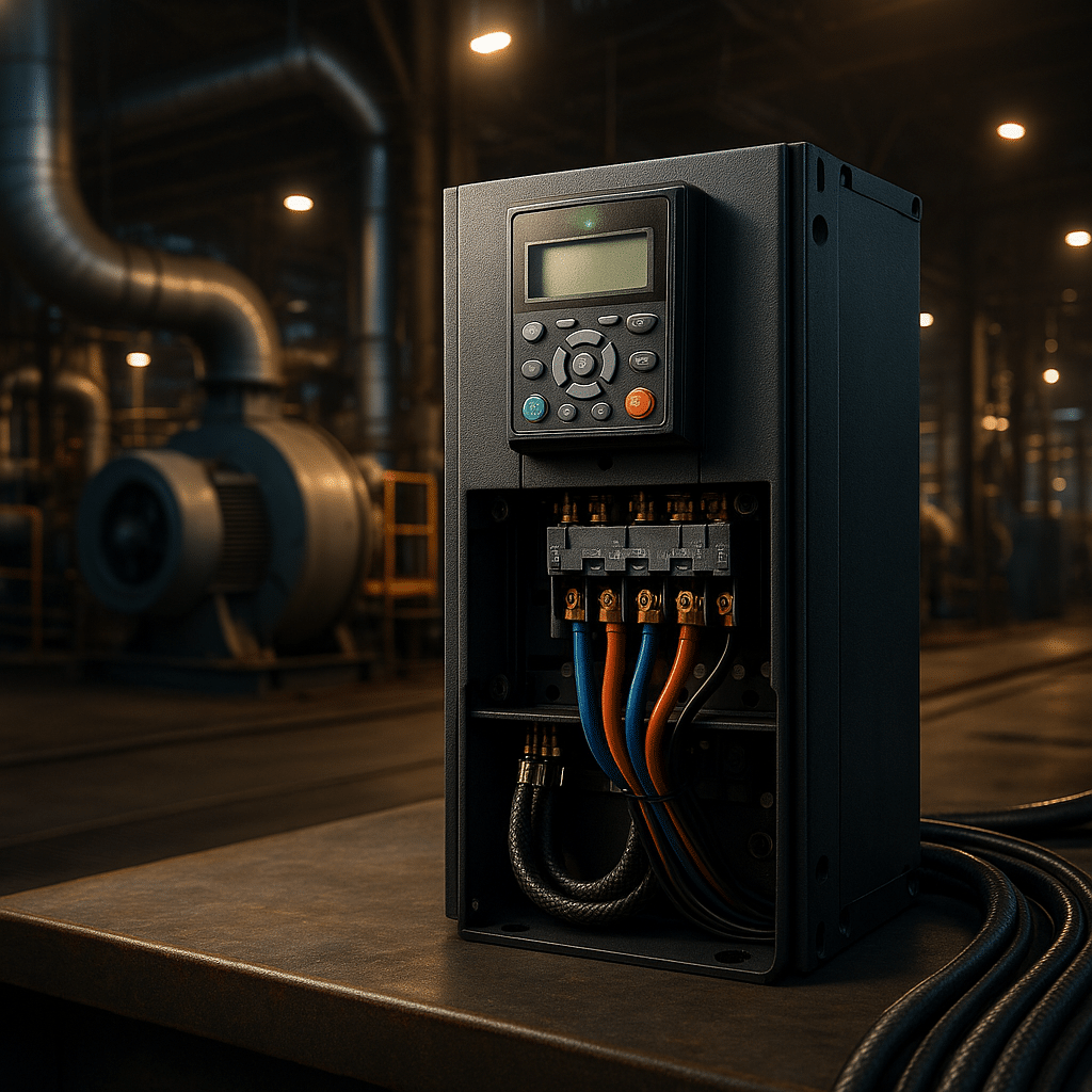
Frequency drive controller installed in modern industrial cabinet
How Do Drives Work?
Internally, a frequency drive uses three main stages: a rectifier, a DC bus, and an inverter. It converts incoming AC power to DC, conditions it, and then uses high-speed switches (IGBTs) to produce a new AC output at a variable frequency. The output is a Pulse Width Modulated (PWM) signal, designed to simulate a sine wave suited for motor control.
Most frequency drives follow a V/Hz ratio to maintain magnetizing current. More advanced models offer vector control and sensorless feedback for precise torque delivery, even at low speeds. Some premium VFD controllers even achieve full torque at 0 RPM without requiring encoders.
Key Frequency Drive Benefits
Frequency drives offer a wide range of industrial and commercial advantages:
Energy Efficiency: Reduce motor energy use by 30-50% on fans, pumps, and compressors.
Soft Starting: Minimize inrush current and reduce wear on mechanical components.
Process Control: Enable precise flow, pressure, or temperature regulation via built-in PID controllers.
Maintenance Savings: Lower downtime and extend motor life by running at optimized speeds.
Improved Safety: Many models include Safe Torque Off (STO) compliant with SIL2/SIL3 standards.
For example, a bottling plant using a spare Yaskawa GA500 frequency drive avoided $42,000 in losses during an unexpected failure—showcasing the reliability and value of modern drives.
Real-World Frequency Drive Applications
Across industries, adjustable speed drives are used to enhance reliability and efficiency. Some notable examples:
Municipal Water Plants: Retrofitting fixed-speed pumps with inverter drives reduced energy use by 30% and halved peak demand [case study].
HVAC Systems: Buildings using ABB ACS580 drives on air handlers reported annual savings of $150k+.
Manufacturing: A pulp & paper plant cut unplanned downtime by 76% after upgrading to modern drive controllers.
Top Drive Manufacturers
Whether you’re sourcing a variable speed drive or high-performance motor controller, these brands dominate the market:
ABB: Known for DTC control and rugged ACS series (180 to 880 models).
Yaskawa: Leading reliability and lifetime performance with GA500/GA800 drives.
Eaton: Feature-rich and affordable with DG1, DM1, and HVAC-ready H-Max lines.
Lenze: Compact modular drives ideal for OEMs and packaging machinery.
Hitachi: Cost-effective motor speed controllers with built-in filters and simple UI.
How to Choose the Right Drive
To ensure optimal results, match the drive to your motor, load profile, and environment. Key criteria include:
Voltage & HP Rating: Confirm the drive handles your motor’s voltage and full-load current.
Duty Class: Choose heavy-duty if your system sees frequent peaks or startups.
Enclosure Type: For dusty or outdoor use, consider NEMA 4X/IP55 drives.
Safety Needs: Ensure STO or other safety certs like IEC 61800-5-2 compliance.
Harmonic Mitigation: Use line reactors or select drives with built-in chokes.
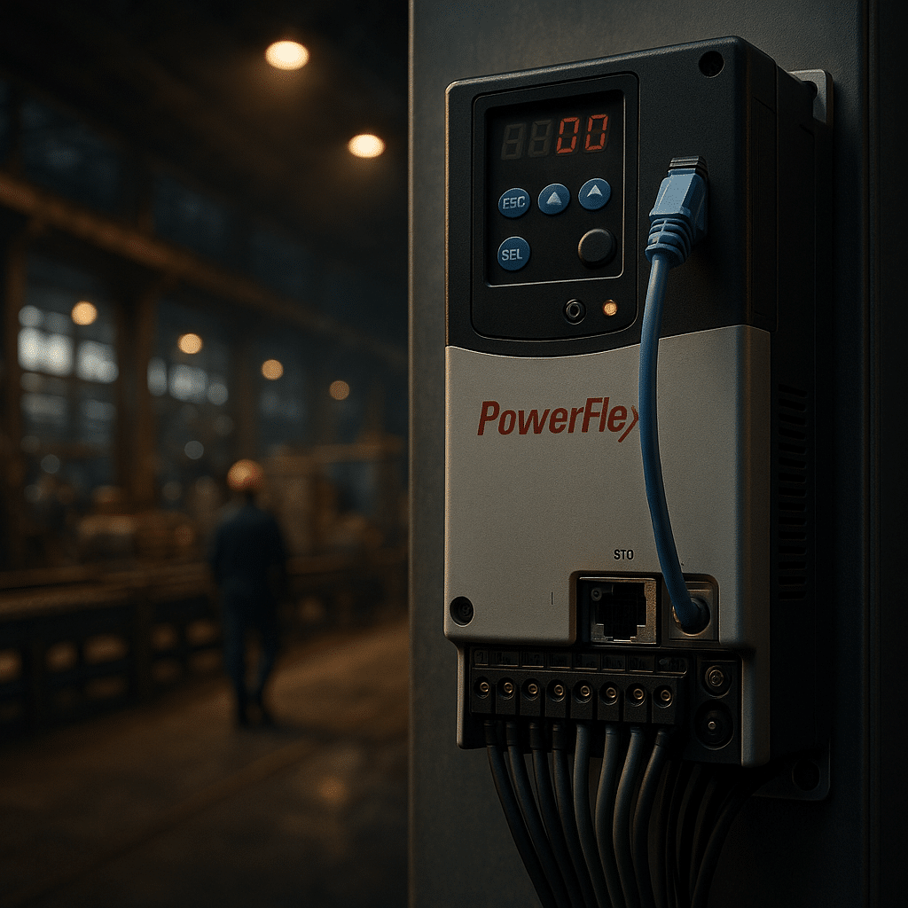
Allen Bradley Power Flex 525 is a compact, network-ready AC drive that delivers efficient, safe motor control without complicating commissioning. It combines sensorless vector control, optional closed-loop feedback, dual PID, and Safe Torque Off to handle both variable‑torque and constant‑torque loads. Because the drive ships with embedded EtherNet/IP and a USB‑powered, “MainsFree” configuration mode, teams can stage spares and deploy quickly. Moreover, the platform covers 0.5–30 hp across global voltages, includes a standard brake chopper, and uses conformal coating for harsher environments. Consequently, many OEMs standardize on this platform when they want tight Logix integration and dependable field service. For a deep spec sheet, see the official PowerFlex 520 series technical data and the summarized product brochure.
What The Allen Bradley Power Flex 525 Does
At its core, the Allen Bradley Power Flex 525 regulates motor speed by controlling the applied voltage and frequency. However, it goes far beyond basic V/Hz control. With sensorless vector control, the drive estimates rotor flux and produces higher starting torque and quicker response. Additionally, you can add an encoder option to run closed‑loop vector control for accurate speed holding and consistent indexing. Furthermore, the integrated dual PID loops let maintenance teams regulate process variables—such as pressure or flow—directly in the drive. Because the control module supports USB “MainsFree” programming, technicians can configure units at a desk, clone multiple devices, and deploy confidently. Finally, built‑in Safe Torque Off (STO) provides a certified Category 0 stop without cycling main power, which shortens recovery time after a safety event and reduces wiring. For fundamentals, our primer on variable frequency drives provides helpful background before you dive into parameters.
If you prefer step‑by‑step setup, start with our VFD programming guide, then map I/O using the on‑drive status screens. Moreover, when your application involves pumps or fans, review our focused article on VFDs for pumps to leverage the internal PID, sleep mode, and pipe‑fill strategies—features that the PowerFlex 525 handles well. In every case, document baseline current draw and speed range so you can verify improvements after commissioning.
Common Causes And Practical Solutions
Improper deceleration is a frequent cause of DC‑bus overvoltage. Therefore, enable the internal brake transistor and size an external resistor when the load has high inertia or frequent stops; if symptoms persist, our troubleshooting guide on overvoltage during decel explains practical resistor sizing. Additionally, long motor leads can create reflected‑wave stress, so installers should apply a dV/dt or sine filter and use inverter‑duty cable. Because heat shortens component life, panels need clean airflow and realistic ambient limits; derate above 50 °C and consider the optional fan kit for hotter spaces. Moreover, miswired control inputs are a common startup issue: verify source versus sink logic, confirm 24 VDC reference and common, and use the input‑status display during I/O checkout.
Finally, harmonic distortion on weak feeders may require line reactors or an active filter to meet IEEE 519; larger PF525 frame sizes include a DC choke that improves current waveform quality. For broader reliability, review our quick diagnostics on VFD overheating and ground‑fault trips, and remember that Precision Electric offers full electric motor repair if testing reveals motor‑side defects. As a result, most nuisance trips disappear once decel ramps, braking, cabling, and cooling are addressed.
Allen Bradley Power Flex 525 VFD: Compact footprint, EtherNet/IP, and Safe Torque Off streamline commissioning.
Configuration, Safety, And Networking For The Rockwell PowerFlex 525
The drive arrives ready for networks. It provides an embedded EtherNet/IP port for cyclic control, diagnostics, and Automatic Device Configuration, so a replacement can inherit parameters from the PLC. Moreover, an RS‑485 port supports DSI and Modbus RTU for multidrop applications, which helps on cost‑sensitive retrofits. As for safety, dual‑channel STO meets SIL 2/PL d when wired correctly and removes gate signals to the output stage to prevent torque generation. In practice, the function integrates with an e‑stop or guard switch for a Category 0 stop. Furthermore, StepLogic sequences and an energy‑optimizer reduce PLC code on small machines and trim magnetizing current at light loads. Because the firmware also supports permanent‑magnet motors, users can leverage high‑efficiency designs without changing the platform. For manufacturer specifics, consult the official PowerFlex 525 specifications.
Practical Control Modes
V/Hz works for general‑purpose fans and pumps. However, sensorless vector control unlocks higher torque at low speed and faster recovery from load changes. Additionally, closed‑loop vector with an encoder improves speed regulation for indexing conveyors and extruders. As a result, builders can hold line speed within tight limits, even as viscosity or tension shifts. Moreover, the dual PID loops manage process feedback and trim setpoints without a separate controller. Consequently, integrators often map one loop to pressure while the second loop supervises temperature or provides cascade control. Finally, ride‑through features maintain operation during short sags by using the spinning motor as an energy source, and a “half‑bus” mode can continue reduced speed during deeper dips. For competitor context, compare Lenze’s i550 feature set on the i550 product page.
Maintenance And Lifecycle Tips
Plan for ventilation and dust control, then verify that heat‑sink fins stay clear. Additionally, keep a parameter backup on a laptop or secured server, and enable Automatic Device Configuration so a spare inherits the exact setup. Because electrolytic capacitors age, schedule a health check at the ten‑year mark or during major shutdowns. Moreover, check braking‑resistor wiring periodically and confirm the thermal contact is intact. For safety, test both STO channels during annual lockout validations and record the results. Finally, trend current, bus voltage, and fault codes from the PLC; early warnings reduce downtime and help target root causes. For a manufacturer contrast on longevity and microdrive design, see Eaton’s DM1 documentation (DM1 overview PDF) and Yaskawa’s GA500 details on the GA500 product page.
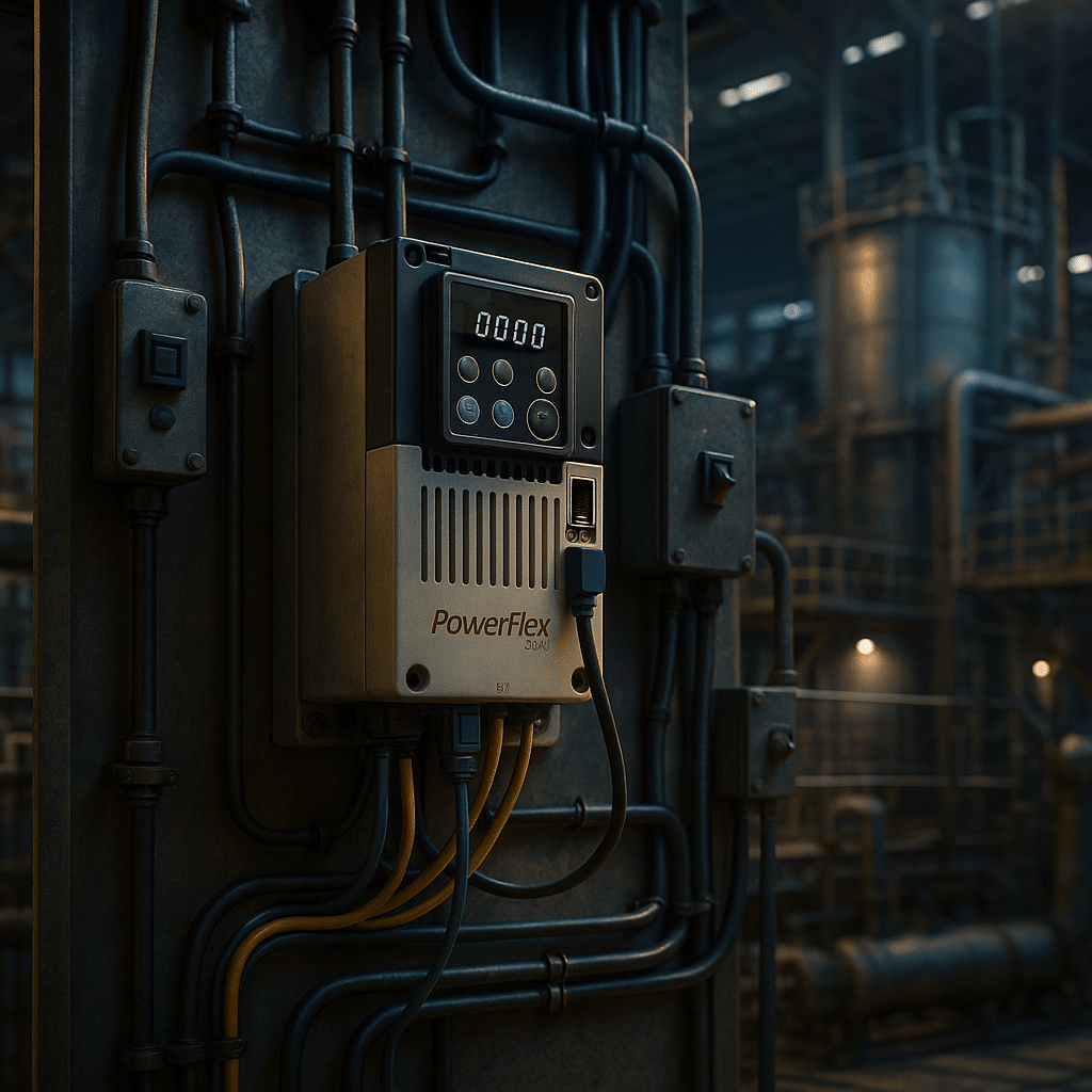
PowerFlex 525 installation essentials: input impedance, output filtering, and braking improve stability and uptime.
Product Recommendations And Sizing For The PowerFlex 520 Series
Start with motor full‑load current and duty class. Choose a Normal Duty size for variable‑torque loads, and select a Heavy Duty rating for conveyors, mixers, and lifts. Next, include input impedance for harmonic control, then specify an output load reactor or a dV/dt filter when motor leads exceed manufacturer guidance. Additionally, budget for a braking resistor when fast deceleration or vertical loads demand it. Because networking saves hours, standardize on EtherNet/IP where possible and reserve the RS‑485 port for simple multidrop retrofits. Finally, document parameter sets for different operating profiles so maintenance can swap recipes without hunting through the menu. To browse categories and accessories, start with core AC variable frequency drives, add input line reactors and output load reactors, and compare brands like ABB, Yaskawa, and Eaton.
Conclusion: When To Choose
Select this platform when you need a compact footprint, native EtherNet/IP, and integrated safety. It fits pumping, conveying, and light positioning duties while keeping commissioning simple. Moreover, the feature set rivals competitors such as Yaskawa GA500, ABB ACS580, Eaton DM1, and Lenze i550, yet the Logix integration often lowers lifecycle cost in Rockwell‑centric plants. If your application requires SIL 3 safety over network, consider the PowerFlex 527 or add external safety hardware. Otherwise, the PowerFlex 525 drive provides the right balance of capability, price, and serviceability for day‑to‑day production. For energy‑optimization tips that apply to this class of drives, review Rockwell’s article on evaluating motor and drive efficiency.
Read The Full Allen Bradley Power Flex 525 Research:
https://www.precision-elec.com/wp-content/uploads/2025/08/allen-bradley-power-flex-525-panel.png10241024Craig Chamberlinhttps://www.precision-elec.com/wp-content/uploads/2025/02/Precision-Electric-Logo-TEXT-ONLY-Color-NEW.pngCraig Chamberlin2025-08-31 09:01:002025-09-18 11:44:30Allen Bradley Power Flex 525 — Specs, Setup, And Best Uses
Plant managers, OEM engineers, and maintenance teams share a common goal: keep production flowing while reducing waste. A Yaskawa frequency drive makes that mission easier. The drive converts fixed utility power into a flexible, pulse‑width‑modulated output, so any standard AC motor can match real‑time process demands. Consequently, systems run only as fast as necessary, equipment lasts longer, and electricity bills shrink. Moreover, Yaskawa backs each unit with a century of R&D success and one of the lowest field‑failure rates in the industry, which means you install confidence—not risk—into every panel.
How a Yaskawa Frequency Drive Works
When three‑phase line power enters the rectifier, diode or IGBT bridges create a stable DC bus. Next, the inverter chops that bus into a variable‑frequency, variable‑voltage waveform that the motor perceives as clean three‑phase power. Therefore, speed is directly proportional to frequency, while advanced vector control maintains torque under load. Yaskawa embeds auto‑tuning routines that fingerprint motor inductance within sixty seconds, so technicians achieve two‑hundred‑percent starting torque without encoders.
Because dual microprocessors split real‑time current loops from diagnostics, the drive reacts to load changes in under two milliseconds. Safe Torque Off circuitry—certified to SIL3 and PL e—disconnects gate signals so the motor cannot generate torque during an emergency stop. These hardware details explain why engineers trust a Yaskawa frequency drive as the heart of their motion system.
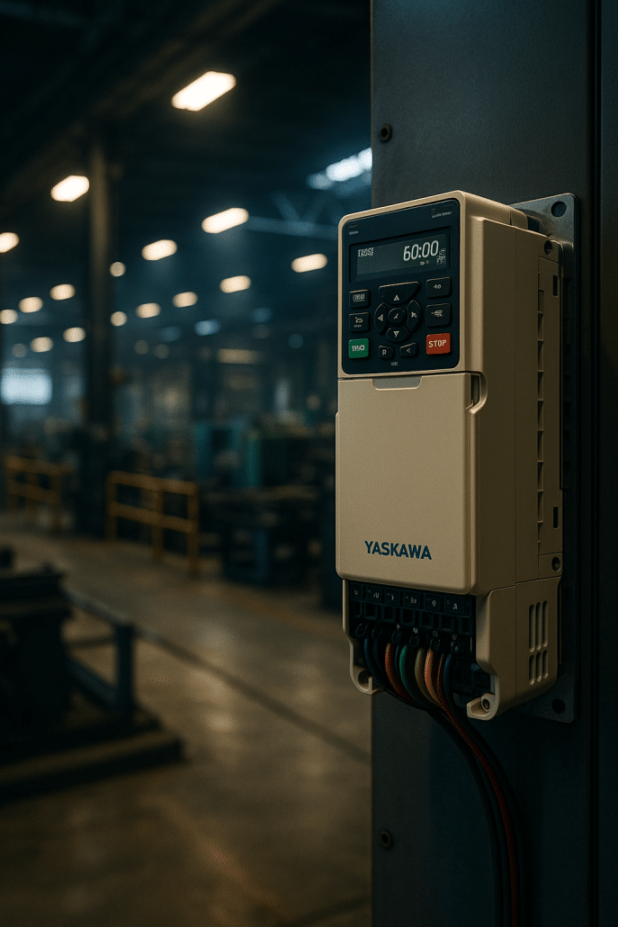
High‑efficiency yaskawa frequency drive GA800 in a rooftop air‑handler panel
Core Features and Industry Standards
Because uptime matters, every series of Yaskawa VFDs includes conformal‑coated boards, a speed‑search restart algorithm, and capacitor‑life monitors that warn long before failure. The electronics meet IEC 61800‑5‑1 safety and EN 61800‑3 EMC, while UL 61800‑5‑1 listing simplifies North‑American inspections. Furthermore, optional IP66 enclosures protect food‑processing lines. Communication cards support Modbus, EtherNet/IP, PROFINET, and EtherCAT, so the drive talks fluently to Rockwell, Siemens, or Beckhoff PLCs.
An intuitive LCD keypad matches parameter groups inside DriveWizard PC software, allowing you to clone setups via USB in seconds. For power‑quality compliance, the GA800 ships with a 3 % DC reactor already installed, and twelve‑pulse or eighteen‑pulse packages meet demanding IEEE 519 sites. If you need regeneration, the U1000 Matrix drive returns braking energy while drawing near‑sinusoidal input current. Competitors offer similar options; however, Yaskawa combines them in a compact footprint and backs them with global support.
Space‑saving GA500 Yaskawa variable frequency drive for OEM skids
Benefits and Real‑World Results
End users consistently record double‑digit savings. For instance, a Midwest grain facility replaced across‑the‑line conveyors with GA800 units and observed a forty‑two percent energy drop—enough to cancel a costly service‑entrance upgrade. Likewise, a Columbus water plant retrofitted booster pumps and logged a thirty percent reduction in kilowatt‑hours during the first year. Because the drives ramp smoothly, pipe hammer vanished and seal life doubled. In packaging, a plastics extruder tightened thickness tolerance and cut scrap by ten percent after switching to sensorless‑vector Yaskawa drives.
Beyond efficiency, the drives extend equipment life. Soft starts remove mechanical shock, while predictive counters track fan run time, internal temperature, and bus‑capacitor ripple, prompting service before failure. Consequently, a pulp‑and‑paper mill that swapped twenty legacy drives for new Yaskawa models saw unplanned downtime plummet by seventy‑six percent. These metrics prove that the right variable frequency drive delivers measurable value.
Choosing the Right Yaskawa Frequency Drive
Begin by matching motor horsepower and supply voltage. The GA800 handles constant‑torque loads up to 600 HP at 480 V, so crushers, mixers, and conveyors fit perfectly. For variable‑torque fans and pumps, the FP605 trims harmonics and offers embedded BACnet for building automation. OEM builders love the GA500; it reaches forty HP in a body smaller than a paperback. Need full regeneration?
As industries pursue ever‑higher efficiency and smarter automation, the ABB vfd has become a cornerstone of modern motor control. At its core, the ABB variable frequency drive adjusts the frequency and voltage supplied to an AC motor. Allowing precise speed regulation and significant energy savings. Because centrifugal loads such as pumps and fans obey the affinity laws. Reducing motor speed by only 20 percent can slash power use by roughly 50 percent.
Therefore, facility managers now regard variable‑speed control as low‑hanging fruit for both carbon‑reduction and cost‑reduction programmes. ABB has led the drives market for decades, yet many technicians still ask how an ABB solution stacks up against popular alternatives. This article explains why an ABB‑branded controller remains a safe, forward‑looking investment, outlines key specifications. It also compares competitive products, and shares real‑world performance data.
Why Choose ABB VFD Technology
First, ABB’s Direct Torque Control (DTC) algorithm delivers full motor torque in milliseconds without requiring an encoder. Consequently, machines such as extruders and winders gain lightning‑fast response while avoiding the complexity of feedback devices. Secondly, ABB embeds safety functions like Safe Torque Off (STO) to SIL 3 / PL e inside the drive. Eliminating external contactors and wiring.
Moreover, every modern ABB inverter ships with on‑board energy calculators that show live kilowatt savings directly on the keypad. The ABB vfd family also integrates DC chokes or active‑front‑end rectifiers that help users comply with IEEE 519 harmonic limits. Even ultra‑low‑harmonic variants achieve total harmonic distortion below five percent. For engineers who need proof, the ABB low‑voltage AC‑drives datasheet lists measured input‑current THD levels as low as three percent.
In addition, ABB’s “all‑compatible” platform unifies parameter‑menu structures from 0.25‑horse‑power micro‑drives up to multi‑megawatt common‑DC systems. Because the same PC tool—DriveComposer—or the DriveSize selection software covers the whole range. This allows technicians to face a gentler learning curve. Finally, global support centres in more than 100 countries ensure spare parts and field service remain. Available throughout a drive’s multi‑decade life‑cycle.
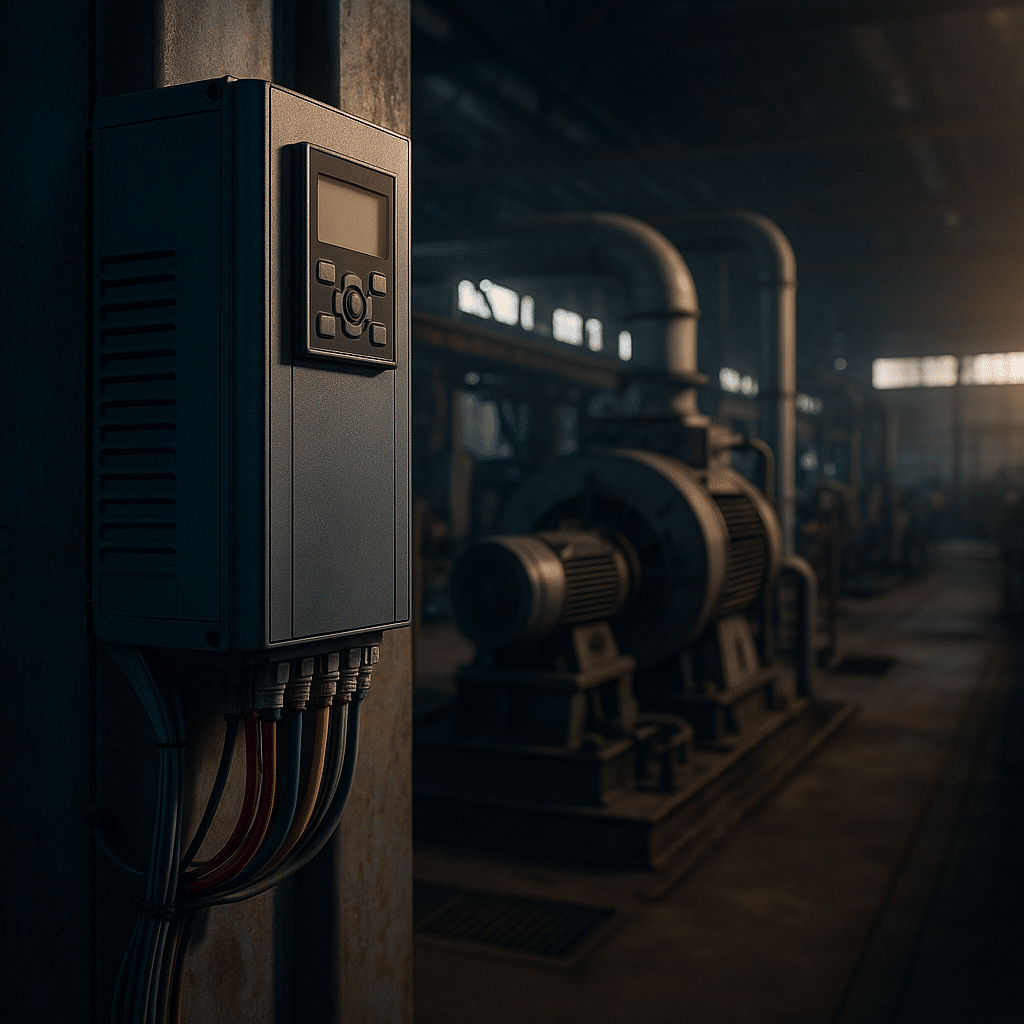
ABB VFD installation boosts pump energy efficiency.
ABB VFD Technical Specifications
Across the low‑voltage portfolio the power range spans 0.18 kW to 5 600 kW at 208–690 VAC. Medium‑voltage models extend ratings into the tens of megawatts. Output‑frequency capability typically covers 0–500 Hz, and many units allow 599 Hz for high‑speed spindles. When engineers select an ABB VFD drive, two duty classes are available. These include Normal Duty (110 percent overload for one minute) and Heavy Duty (150 percent overload for one minute). Ambient temperatures up to 40 °C require no derate, yet the drive can operate at 50 °C with additional fan assistance. Altitude correction factors begin above 1 000 m. To mitigate electromagnetic interference, EMC filters meeting IEC 61800‑3 categories C2 or C3 are factory‑installed. While ultra‑low‑harmonic active‑front‑end converters are offered for grids that demand THD < 5 percent.
Efficiency matters as well. According to the IEA‑4E VSD efficiency study, almost all modern variable‑speed drives already surpass the IE2 efficiency class defined in IEC 61800‑9‑2. Typical ABB losses stay 30–50 percent below the IE2 ceiling, translating to drive efficiencies around 97–98 percent at full load. Because less heat must leave the enclosure, panel builders can down‑size cooling hardware and reduce total installed cost.
ABB VFD vs Competitors
How does an abb vfd compare with other market leaders? Yaskawa’s GA800 series enjoys a reputation for legendary reliability, yet it lacks the built‑in harmonic mitigation found in many ABB AC drive models. Danfoss positions its VLT range squarely at HVAC, offering dedicated fire‑mode features that mirror ABB’s ACH 580. The Eaton PowerXL DG1 emphasises Active Energy Control, a voltage‑optimisation routine that adds two‑to‑ten percent extra savings, although ABB implements a comparable flux‑optimisation mode. Hitachi’s WJ200 drive boasts 200 percent torque at 0.3 Hz, yet ABB’s DTC can match that performance sensor‑lessly. Finally, Siemens SINAMICS shines in Totally Integrated Automation environments, whereas ABB remains protocol‑agnostic, supporting EtherNet/IP, PROFINET, Modbus TCP and many others.
Therefore, product selection often hinges on ecosystem fit, harmonic targets and service coverage. If a plant already runs ABB industrial robots, choosing an ABB speed controller reduces the spare‑parts catalogue and unifies engineering tools. Conversely, a facility dominated by Allen‑Bradley PLCs may prefer PowerFlex drives for tighter Studio 5000 integration. Nevertheless, many integrators deploy mixed fleets because modern drives share international standards such as IEC 61800‑5‑2 and UL 61800‑5‑1, ensuring basic interoperability.
Technician configuring ABB VFD for optimal motor control.
Real‑World ABB VFD Case Studies
A U.S. wastewater plant retrofitted its constant‑speed pumps with ABB VFD units and cut energy use by 30 percent. This energy cut is while halving peak demand. The independent evaluation published by the Columbus WWTF VFD case study shows specific energy dropping from 259 kWh / MG to 179 kWh / MG. Because the drives ramp the pumps gently, water hammer was reduced, lowering pipe failures. Similarly, a plastics extruder replaced an ageing DC drive with an ABB frequency converter. After implementation, they observed line‑speed variation shrink from ±2 percent to ±0.4 percent. Yielding a three‑percent scrap reduction. In mining, replacing across‑the‑line starters on a 2 MW conveyor with ABB medium‑voltage drives virtually eliminated belt slip and extended belt life by two years.
Even vertical transportation benefits. When a Midwest hospital installed regenerative ABB variable speed drives on its elevators. Also descending cars fed power back to the building, saving roughly 18 000 kWh per year. Meanwhile, crane operators at a Gulf‑Coast port reported smoother load control and faster cycle times. This is after migrating to ABB multi‑drive hoist packages.
Best Practices for ABB VFD Implementation
Proper sizing begins with accurate motor‑nameplate data. DriveSize software recommends an ABB AC drive that meets the true RMS current of the load profile. Next, observe cable‑length limits or specify dv/dt filters on long leads. Noise immunity depends on good grounding. So bond both ends of the motor‑cable shield to the drive frame and the motor housing. Furthermore, use shielded control wiring and route it away from power conductors. When regenerative braking energy cannot be reused, dimension dynamic‑brake resistors for the peak kinetic load.
Commissioning is equally critical. Always run the adaptive auto‑tune routine so DTC can model the motor precisely. Then, verify that STO wiring meets the required safety category. Finally, record baseline current, voltage and harmonics; these snapshots simplify future troubleshooting and support predictive‑maintenance initiatives.
Recommended ABB VFD Product Categories
Precision Electric stocks the full abb vfd range along with complementary technologies. For general‑purpose automation we suggest the ACS 580 in sizes to 500 kW—see our AC variable‑frequency‑drive catalogue. Heavy‑duty conveyors and grinders often require regenerative capability; in that case the modular ACS 880 fits, and our engineers can package it with input reactors and harmonic filters. When soft‑starting alone suffices, browse our soft‑starter selection. Additionally, if you must power a three‑phase ABB VFD drive from single‑phase supply, explore our rotary phase converters. For troubleshooting tips read our guides on over‑voltage faults, cooling issues, over‑current trips and our ground‑fault article.
Conclusion
The abb vfd remains a proven path to energy efficiency, process stability and equipment longevity. Because ABB combines advanced motor control, integrated safety and a vast power range, the drives deliver results across HVAC, water, manufacturing and heavy industry. By following recognised best practices and selecting the correct options, engineers can maximise ROI and future‑proof their installations.
Introduction: What A Danfoss Variable Frequency Drive Does
A danfoss variable frequency drive (VFD) adjusts motor speed and torque to match real process demand. Instead of running a motor at full speed and wasting energy with dampers or valves, the drive supplies only the frequency and voltage the load requires. Consequently, you lower kilowatt demand, reduce mechanical stress, and increase uptime. In practice, Danfoss combines robust hardware with intuitive software to make these outcomes repeatable. For product scope and documentation, see the official VLT® AutomationDrive FC 301/302 page and the educational primer What is a variable frequency drive?.
Moreover, the VLT AutomationDrive family covers a wide power range and supports induction, permanent‑magnet, and synchronous‑reluctance motors. As a result, you can standardize on one controller for many applications without locking into a specific motor brand. Additionally, features such as Automatic Motor Adaptation (AMA) and Automatic Energy Optimization (AEO) shorten commissioning and capture extra efficiency at partial load. Importantly, Danfoss emphasizes power quality and reliability: most models ship with integrated DC‑link chokes and RFI filters to curb harmonics and electromagnetic emissions.
Furthermore, rugged options such as conformal coating, high ambient temperature ratings, and back‑channel cooling help the electronics survive harsh conditions. Finally, when you pair a danfoss variable frequency drive with inverter‑duty motors and sound installation practices, you protect the entire system—from breakers and transformers to bearings and seals.
Why Variable Speed Saves Energy In Pumps And Fans
Variable speed saves energy because many loads follow the fan and pump affinity laws. In short, the power required changes roughly with the cube of speed. Consequently, trimming speed by 20% can cut power by ~50% on a centrifugal blower. Likewise, turning down a pump from 60 Hz to 48 Hz often delivers the same flow with dramatically less input power. Therefore, a danfoss variable frequency drive usually pays for itself quickly in air‑handling units, cooling towers, process pumps, and conveyance fans.
However, energy efficiency is only one benefit. Because a Danfoss AC drive ramps smoothly, it eliminates across‑the‑line inrush and reduces belt slip, water hammer, and pressure spikes. Moreover, built‑in PID control lets the drive hold setpoints for pressure, flow, or temperature without extra controllers. Additionally, sleep/wake functions prevent dead‑heading and idle run time on pump systems. In many facilities, these control features extend mean time between failures and reduce maintenance callouts.
For planning, you should also consider monitoring features. Danfoss provides energy readouts, fault histories, and condition‑based monitoring options so teams can see savings and spot degrading performance early. In the same way, network options—PROFINET, EtherNet/IP, BACnet, and Modbus—simplify integration with existing PLC and BAS systems. For selection help or a quote, review our AC Variable Frequency Drives category.
Danfoss variable frequency drive energy-saving for fan and pump systems
Harmonics, EMC And Standards Compliance
Nonlinear loads, including any danfoss variable frequency drive, draw current in pulses and can inject harmonics into the supply. Therefore, designers reference IEEE 519‑2014 when setting distortion targets at the point of common coupling. In parallel, EMC immunity and emission requirements fall under IEC 61800‑3 for adjustable‑speed drives. Because motor insulation sees fast voltage rise times, NEMA MG 1 Part 31 defines inverter‑duty criteria so motors survive high dv/dt and reflected‑wave peaks on long leads.
To meet these expectations, Danfoss integrates DC‑link chokes and RFI filters as standard on many frames. Consequently, total harmonic current distortion often drops into acceptable ranges without external filters. Furthermore, dedicated low‑harmonic or active front‑end options cancel most remaining harmonic content when utility or generator constraints are tight. Additionally, output dV/dt or sine‑wave filters keep motor terminal voltage within insulation limits, which protects older motors when retrofitting a drive. For practical selection and troubleshooting, see our cornerstone guides on VFD overvoltage on decel, VFD overcurrent, and VFD overheating.
In practice, follow a simple rule set. First, verify short‑circuit ratings, protective device coordination, and enclosure ingress ratings for the site. Second, select cable types approved for VFD outputs and land shields correctly at one end to avoid ground loops. Third, apply line reactors or passive filters when supply impedance is very low, and specify inverter‑duty motors or output filters when cable runs are long. Finally, document the target THD and EMC class so commissioning can confirm compliance. If you need components, explore input line reactors and output load reactors.
INSTALLATION AND COMMISSIONING BEST PRACTICES
Successful projects start with practical details. Begin with a load profile and a realistic minimum speed. Then size the danfoss variable frequency drive for continuous current with the correct overload class for the duty cycle. Next, match the enclosure rating to the environment and plan heat removal; Danfoss back‑channel cooling can eject most waste heat through a duct, which reduces cabinet temperature and improves service life. During commissioning, use Automatic Motor Adaptation to identify motor parameters and enable Automatic Energy Optimization for part‑load savings.
Moreover, program PID, sleep, and minimum‑flow protections before turnover. Additionally, verify digital and analog I/O, fieldbus addresses, and safety circuits such as Safe Torque Off. Because issues often trace to wiring, confirm control commons, shield terminations, and analog scaling before starting a formal autotune. For a step‑by‑step setup overview, review our guide to VFD autotune and our checklist for VFD won’t start—control wiring errors.
For reliability, add the right accessories. Input line reactors mitigate transients and lower harmonic currents when upstream impedance is weak. Output load reactors or dV/dt filters reduce motor stress on long cable runs. Finally, establish a spare‑parts plan that includes a compatible keypad, cooling fans, and a preconfigured spare drive. Consequently, you can swap hardware in minutes while the failed unit goes to repair without extending downtime. If you maintain legacy systems, consider our soft starter and VFD phase converter categories for special use cases.
Danfoss variable frequency drive energy‑saving
Product Recommendations For Common Scenarios
Because needs vary, match features to the job rather than chasing the highest spec sheet. For general industrial machinery and conveyors, a danfoss variable frequency drive with the VLT AutomationDrive FC 302 feature set covers induction and permanent‑magnet motors with sensorless vector control and integrated safety. For building HVAC, choose a Danfoss AC drive with multi‑pump control and BACnet to simplify air and water balancing. Meanwhile, water and wastewater sites benefit from anti‑cavitation and anti‑ragging functions and rugged enclosures. When you are ready to buy, start with our curated Danfoss and multi‑brand VFD catalog.
When multi‑brand comparisons help, evaluate peers on the same criteria. For instance, Yaskawa’s GA800 general‑purpose drive offers broad horsepower coverage and straightforward setup; however, value remains similar when sized and installed with the same best practices. Likewise, ABB highlights the high cost of unplanned downtime—its global survey reports a typical $125,000 per hour impact—which reinforces the case for reliable drives and proactive maintenance (ABB press release). Therefore, base your shortlist on local support, lead time, and accessories as much as on raw performance.
To streamline procurement and maintenance, standardize a core set of frame sizes and option codes across your plant. Additionally, select complementary accessories—line reactors, output reactors, and configured packages—from a consistent supplier. As a result, technicians learn one interface, spares fit multiple assets, and inventory stays lean. Finally, document parameter templates for common motors so replacements restore operation fast and repeatably.
Conclusion: Selecting A Danfoss Variable Frequency Drive
A danfoss variable frequency drive delivers measurable energy savings, tighter process control, and gentler mechanical dynamics. However, the best outcomes come from matching features to the duty, wiring and filtering to the site, and commissioning to the plan. Therefore, treat the drive, motor, and power system as one unit and verify each choice against standards and the environment. In practice, Danfoss combines efficient thermal design, integrated power‑quality hardware, and broad motor compatibility into a dependable platform.
Moreover, the ecosystem of software, option cards, and service support makes scaling from small fans to large process pumps straightforward. Consequently, organizations that standardize on a Danfoss VFD family reduce energy use and downtime while improving safety and compliance. If you need help selecting, sizing, or commissioning, our engineering team can translate requirements into a configured bill of materials and a reliable startup plan.
Read The Full Danfoss Variable Frequency Drive Research: