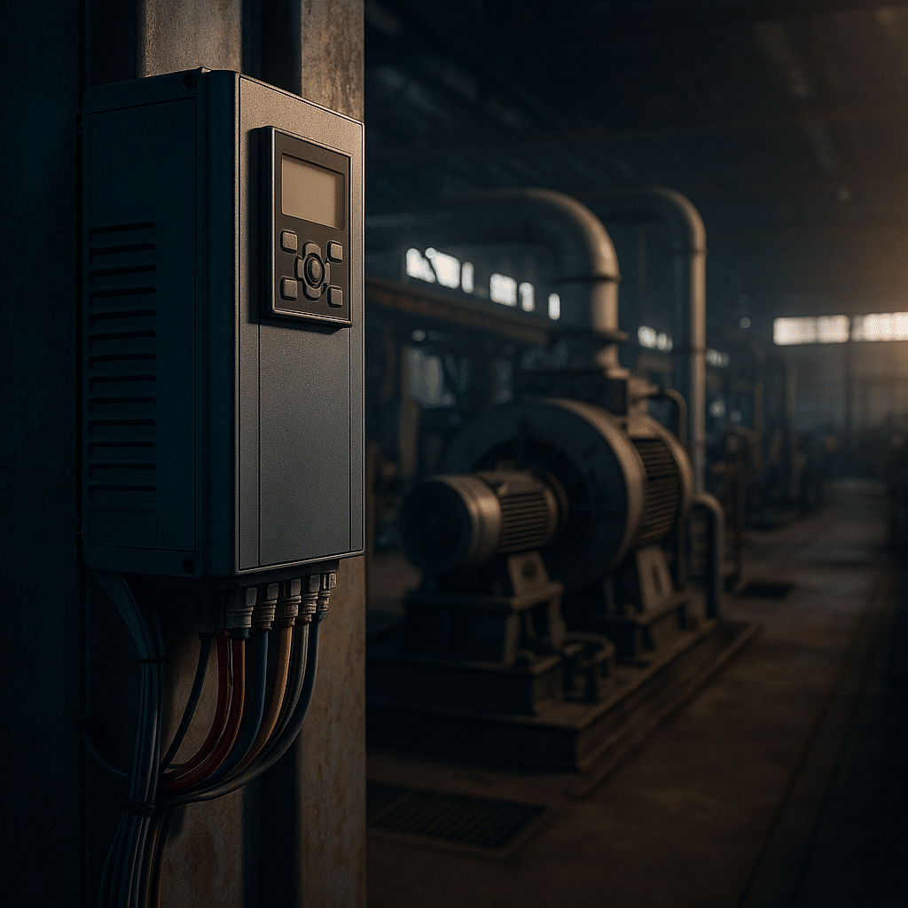
Additionally, many facility managers now recognize that installing a vfd on pumps is an immediate way to curb energy waste, improve reliability, and meet tightening sustainability targets. A Variable Frequency Drive (VFD) varies the motor’s speed so the pump only delivers the flow or pressure the process actually needs. Consequently, the system avoids the old habit of throttling excess flow with valves. That tactic burned electricity and wore out equipment.
Moreover, industry bodies such as the Hydraulic Institute and the U.S. Department of Energy recommend variable speed pumping as best practice. In this article we explain how a VFD works on centrifugal and positive‑displacement pumps. We also list measurable benefits, design guidelines, and proven products from ABB, Yaskawa, Eaton, Hitachi, and Lenze.
Consequently, before we dive deeper, keep in mind that matching speed to demand follows the pump affinity laws: power ∝ speed³. Therefore, dropping speed by only 20 % can slash power by roughly 50 %. That simple math underpins every successful vfd on pumps project.
Why Use a VFD on Pumps?
Furthermore, energy efficiency drives most retrofits. Because pumps consume nearly 20 % of global electricity, even modest speed reductions pay large dividends. Facilities that installed a vfd on pumps routinely report 30–50 % kWh savings. For instance, the City of Columbus wastewater plant cut specific energy from 259 kWh/MG to 179 kWh/MG after the retrofit. The simple change yielded a 30 % reduction.
Similarly, operators gain precise process control. With built‑in PID loops the drive holds pressure, level, or flow set‑points within tight bands. Moreover, soft acceleration eliminates water hammer, while multi‑pump sequencing balances run hours and maintains redundancy.
Likewise, maintenance teams value the gentler, controlled start. As a result, one chemical plant doubled seal life—from six to eighteen months—by replacing a throttling valve with automatic speed control.
Energy Savings from a VFD Pump System
Subsequently, because power falls with the cube of speed, the economic argument is compelling. Moreover, many utilities offer rebates that shrink payback to less than two years. Still, managers sometimes overlook demand charges. Fortunately, a vfd on pumps also halves inrush current, cutting peak demand and generator sizing requirements.
Consequently, for deeper technical reading you can review our internal guide on VFD overvoltage faults. You can also consult the external USU irrigation study that quantifies real‑world savings.
Process Control with Variable Frequency Drive on Pumps
Additionally, variable speed opens the door to dynamic pressure reset and sensorless flow algorithms. Consequently, HVAC systems that once suffered overflow can now modulate flow precisely, improving chiller ΔT and tenant comfort.
Moreover, to see how precise control prevents nuisance trips, read our troubleshooting note on VFD overheating.
Reduced Mechanical Stress
Consequently, soft‑start eliminates the six‑times‑FLA inrush typical of across‑the‑line starts. Pressure rise stays gentle and water hammer disappears.
Therefore, life‑cycle cost models that include maintenance often show the VFD paying for itself twice by year five.
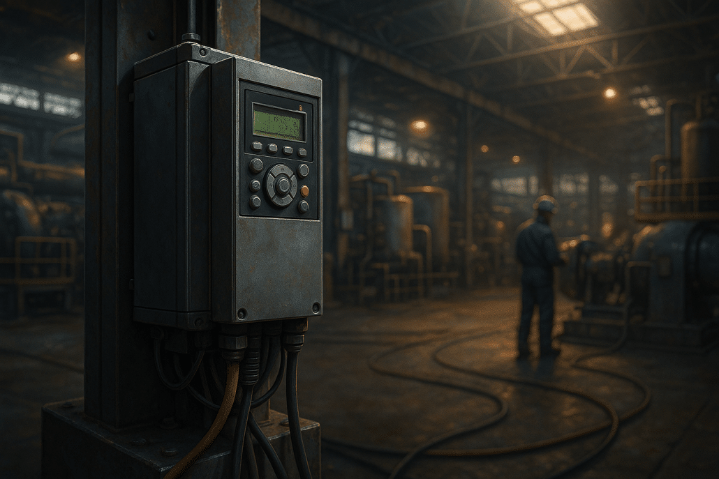
Pump power falls with the cube of speed — a key reason to use a VFD on pumps.
Technical Considerations for Implementing a VFD on Pumps
Additionally, before ordering hardware, size the drive for variable‑torque duty and verify the motor is inverter‑duty per NEMA MG1 31. Also, add dV/dt filters on cable runs longer than 100 ft.
Moreover, evaluate harmonics. According to IEEE 519, voltage THD at the point of common coupling should stay below 5 %. Drives such as the ABB ACQ580 include built‑in chokes, yet large stations may require an active filter.
Furthermore, plan control integration. Because most modern VFDs embed PID control, you can often skip a separate PLC for simple booster sets. Nevertheless, mission‑critical plants still add a bypass contactor for redundancy.
Consequently, for more commissioning tips, see our article on VFD autotune, which explains how an autotune aligns motor parameters for stable low‑speed operation.
Real‑World Examples of VFD Projects on Pumps
Likewise, the Town of Mooresville cut pumping energy while enabling two water plants to operate cooperatively after adding an Eaton SC9000 medium‑voltage drive.
Similarly, a wastewater utility in Columbus trimmed 30 % of influent‑pump kWh, while the wet‑well level strategy boosted storage and deferred capital.
Consequently, a chemical plant installing an ABB ACS580 reduced vibration and doubled seal life.
Meanwhile, an irrigation system powered by photovoltaics rides through cloud events gracefully because the Hitachi solar‑ready drive modulates speed in real time.
Recommended VFD Product Lines for Pump Service
Furthermore, below are trusted categories available from Precision Electric. Each link opens our catalog for immediate selection:
Moreover, for municipal boosters consider the ABB ACQ580; for lift‑stations the Yaskawa iQpump1000 offers auto‑clean routines.
Installation of a VFD on pumps improves energy efficiency and control.
Conclusion and Next Steps
Hence, in summary, a well‑applied vfd on pumps delivers verifiable savings, smoother control, and longer equipment life. Because the drive matches speed to demand, the pump never works harder than necessary.
Therefore, whether you manage a dairy farm, a data‑center chilled‑water loop, or a city utility, adding a VFD should sit high on your improvement list.
Finally, ready to go further? Download our full 14‑page research report for engineering calculations, wiring diagrams, and case‑study KPIs.
https://www.precision-elec.com/wp-content/uploads/2025/07/vfd-on-pumps-graphic1.png10241536Craig Chamberlinhttps://www.precision-elec.com/wp-content/uploads/2025/02/Precision-Electric-Logo-TEXT-ONLY-Color-NEW.pngCraig Chamberlin2025-07-26 09:01:002025-07-17 14:11:17VFD on Pumps: Complete Guide to Energy Savings and Control
As a danfoss frequency drive, the drive adjusts motor speed by changing output frequency and voltage. Accordingly, it lets you match pump, fan, or conveyor speed to real demand instead of wasting energy with throttling. Additionally, this approach cuts wear during starts and stops and stabilizes process control for repeatable quality.
For a quick orientation, see the VLT AutomationDrive and the VLT AQUA Drive lines. Also, independent studies report average energy savings of about 43% in variable‑flow systems when operators deploy a danfoss frequency drive or similar VFD, with payback often under a year; as a result, facilities usually recover cost quickly via lower kWh consumption (study summary).
Consequently, you improve uptime too. Moreover, modern platforms add built‑in chokes, EMI filters, and safety functions to streamline compliant installations. This overview distills the attached research into practical guidance you can use today.
Additionally, you can deepen foundational knowledge at our internal learning pages: start with the concise VFDs overview and keep the VFD programming guide handy for day‑one commissioning checklists. Equally, when legacy assets fail, our VFD replacement guide outlines drop‑in strategies that shorten downtime.
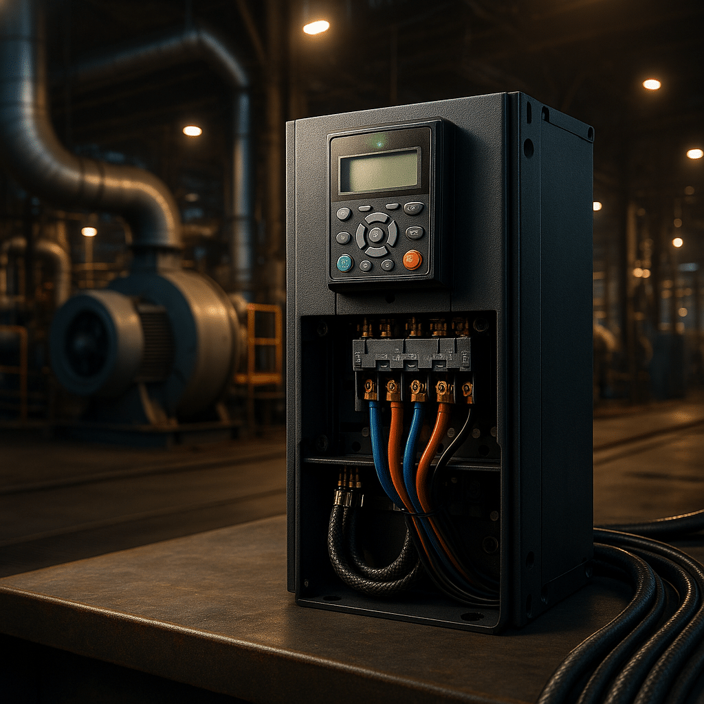
Danfoss frequency drive overview: energy savings with VLT drive control
Causes Of Inefficiency & Practical Solutions
First, oversizing and constant‑speed operation inflate energy bills. Accordingly, a danfoss frequency drive trims speed to the exact process setpoint using onboard PID. Also, Automatic Energy Optimization reduces magnetizing losses at partial load, which compounds the classic affinity‑law savings noted in the research.
Second, hard starts and stops stress shafts, belts, and impellers. Consequently, ramped acceleration and deceleration reduce mechanical shock while skip‑frequency bands avoid resonance in fans and blowers. In addition, robust thermal design and conformal coating on many models extend life in dusty or humid rooms, so maintenance intervals lengthen.
Third, poor integration slows projects. Accordingly, Danfoss offers modular fieldbus options such as BACnet, Modbus, EtherNet/IP, and PROFINET, so you can drop the motor speed controller into almost any architecture. For hands‑on commissioning, our VFD autotune guide and VFD programming guide walk through parameter sets that speed startup and stabilize loops.
Finally, many plants struggle with harmonics and EMI. Accordingly, integrated DC link chokes and RFI filters help typical installations satisfy power‑quality and EMC goals with fewer external parts. In addition, you can reference ABB’s downtime economics ($125k per hour) to justify best‑practice filtering and spares, because the avoided outage usually dwarfs the incremental hardware cost.
Advanced Features & Standards In A Drive
Also, safety matters. Accordingly, Safe Torque Off removes torque without external contactors, which simplifies e‑stop circuits and supports functional‑safety compliance. Furthermore, integrated reactors and RFI filters help many installations meet IEEE‑519 harmonic targets and IEC/EN 61800‑3 EMC categories right out of the box, which reduces panel space and cost.
Equally important, motor insulation must match PWM output from any industrial frequency drive. As a result, pair a danfoss vfd with an inverter‑duty motor that follows NEMA MG1 Part 31 guidance; for details, review this concise NEMA MG1 explainer. In long‑cable runs or with legacy motors, a dV/dt or sine‑wave filter protects windings and bearings.
Additionally, reliability counts. Accordingly, back‑channel cooling exhausts most heat directly, which reduces cabinet HVAC and extends component life. For HVAC and water projects, the purpose‑built VLT AQUA Drive integrates multi‑pump control and anti‑water‑hammer ramps, so operators maintain stable pressure with fewer nuisance trips.
Finally, digital readiness matters. Accordingly, built‑in diagnostics and condition‑monitoring counters make the danfoss inverter an effective edge sensor for motors and pumps. In addition, data logging of current, temperature, and fault histories speeds root‑cause analysis, which shortens repair time and improves uptime. These capabilities align well with modern reliability programs.
Real-World Results & Cross-Brand Context For Variable Frequency Drives
In practice, plants see measurable gains. As an illustration, independent testing shows variable‑speed pumping often saves 19–55% energy on average (pumping study). Additionally, fewer mechanical shocks increase MTBF across couplings and bearings, so you avoid overtime and emergency callouts.
Comparatively, ABB, Yaskawa, Eaton, Hitachi, and Lenze supply capable alternatives. Also, ABB highlights the staggering cost of downtime at $125k per hour, which underscores investing in robust hardware and service. Meanwhile, Yaskawa markets long MTBF for compact drives (field example), and Eaton’s legacy SVX9000 units share Danfoss DNA (replacement note).
Therefore, selection hinges on environment, network, and service. In addition, our VFD replacement guide explains drop‑in swaps when obsolescence emerges, and our VFDs overview outlines where each industrial frequency drive excels. Equally, our in‑house team supports repairs and retrofits when schedules are tight.
Finally, procurement timing matters. Accordingly, if one brand is backordered, you can often deploy an equivalent vlt drive or compatible vacon drive with minimal wiring changes. As a result, you preserve throughput while standardizing later during a planned outage. This flexible approach keeps projects on time and within budget.
Danfoss frequency drive overview—VLT drive benefits for pumps and fans
Recommended Products & Categories For A Project
For new builds or upgrades, start with a right‑sized variable frequency drive. Accordingly, browse our AC variable frequency drives catalog and request help sizing to duty cycle, enclosure, and overload class. Also, specify enclosure and EMC category up front to minimize rework and change orders.
Next, plan power quality. As a result, many panels benefit from input line reactors and output load reactors to cut harmonics and limit dV/dt at the motor. Additionally, legacy across‑the‑line starters are often replaced with modern soft starters for fixed‑speed loads while the danfoss frequency drive handles variable‑speed assets.
Finally, map commissioning and support. Accordingly, our in‑house team can program parameters, tune loops, and repair electronics; for service details, see Precision Electric motor repair and the VFD programming reference. In addition, you can consult Danfoss product docs such as the VLT AutomationDrive to confirm ratings, safety functions, and fieldbus options.
As a closing tip, document parameters before any swap. Accordingly, keep a file or panel copy of the current configuration so engineers can reproduce behavior on new hardware fast. As a result, you minimize retuning, avoid unexpected trips, and return to production sooner.
Conclusion
All told, a danfoss frequency drive delivers efficient speed control, stronger uptime, and straightforward compliance. Accordingly, Danfoss packages safety, filtering, and robust cooling so you can focus on process results instead of hardware babysitting. This balanced design shortens integration time and reduces the need for extra panel components.
Consequently, teams that adopt this approach cut energy, reduce maintenance, and improve quality across pumps, fans, and conveyors. In addition, cross‑brand knowledge and a clear lifecycle plan simplify replacements when parts age out. If you want a short path from specs to savings, our engineers can help design, commission, and support your next danfoss ac drive rollout.
In industrial automation and motor control, the frequency drive—commonly known as a VFD (variable frequency drive)—has become an essential component for energy savings, precision, and process efficiency. This guide breaks down what frequency drives are, how they work, and how to choose the right type for your industrial application.
What Is a Frequency Drive?
A frequency drive is an electronic device that controls the speed and torque of an AC motor by varying the frequency and voltage of its power supply. Also known as an inverter drive or motor speed controller, it allows motors to operate efficiently across a wide range of speeds, rather than being limited to full-speed or off.
Traditional motor systems often waste energy by throttling mechanical output. In contrast, a variable frequency drive adjusts motor speed to match real-time load demand—cutting energy consumption dramatically.
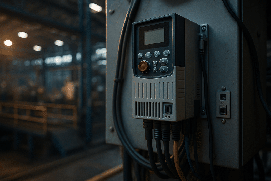
Frequency drive controller installed in modern industrial cabinet
How Do Drives Work?
Internally, a frequency drive uses three main stages: a rectifier, a DC bus, and an inverter. It converts incoming AC power to DC, conditions it, and then uses high-speed switches (IGBTs) to produce a new AC output at a variable frequency. The output is a Pulse Width Modulated (PWM) signal, designed to simulate a sine wave suited for motor control.
Most frequency drives follow a V/Hz ratio to maintain magnetizing current. More advanced models offer vector control and sensorless feedback for precise torque delivery, even at low speeds. Some premium VFD controllers even achieve full torque at 0 RPM without requiring encoders.
Key Frequency Drive Benefits
Frequency drives offer a wide range of industrial and commercial advantages:
Energy Efficiency: Reduce motor energy use by 30-50% on fans, pumps, and compressors.
Soft Starting: Minimize inrush current and reduce wear on mechanical components.
Process Control: Enable precise flow, pressure, or temperature regulation via built-in PID controllers.
Maintenance Savings: Lower downtime and extend motor life by running at optimized speeds.
Improved Safety: Many models include Safe Torque Off (STO) compliant with SIL2/SIL3 standards.
For example, a bottling plant using a spare Yaskawa GA500 frequency drive avoided $42,000 in losses during an unexpected failure—showcasing the reliability and value of modern drives.
Real-World Frequency Drive Applications
Across industries, adjustable speed drives are used to enhance reliability and efficiency. Some notable examples:
Municipal Water Plants: Retrofitting fixed-speed pumps with inverter drives reduced energy use by 30% and halved peak demand [case study].
HVAC Systems: Buildings using ABB ACS580 drives on air handlers reported annual savings of $150k+.
Manufacturing: A pulp & paper plant cut unplanned downtime by 76% after upgrading to modern drive controllers.
Top Drive Manufacturers
Whether you’re sourcing a variable speed drive or high-performance motor controller, these brands dominate the market:
ABB: Known for DTC control and rugged ACS series (180 to 880 models).
Yaskawa: Leading reliability and lifetime performance with GA500/GA800 drives.
Eaton: Feature-rich and affordable with DG1, DM1, and HVAC-ready H-Max lines.
Lenze: Compact modular drives ideal for OEMs and packaging machinery.
Hitachi: Cost-effective motor speed controllers with built-in filters and simple UI.
How to Choose the Right Drive
To ensure optimal results, match the drive to your motor, load profile, and environment. Key criteria include:
Voltage & HP Rating: Confirm the drive handles your motor’s voltage and full-load current.
Duty Class: Choose heavy-duty if your system sees frequent peaks or startups.
Enclosure Type: For dusty or outdoor use, consider NEMA 4X/IP55 drives.
Safety Needs: Ensure STO or other safety certs like IEC 61800-5-2 compliance.
Harmonic Mitigation: Use line reactors or select drives with built-in chokes.
Allen Bradley Power Flex 525 is a compact, network-ready AC drive that delivers efficient, safe motor control without complicating commissioning. It combines sensorless vector control, optional closed-loop feedback, dual PID, and Safe Torque Off to handle both variable‑torque and constant‑torque loads. Because the drive ships with embedded EtherNet/IP and a USB‑powered, “MainsFree” configuration mode, teams can stage spares and deploy quickly. Moreover, the platform covers 0.5–30 hp across global voltages, includes a standard brake chopper, and uses conformal coating for harsher environments. Consequently, many OEMs standardize on this platform when they want tight Logix integration and dependable field service. For a deep spec sheet, see the official PowerFlex 520 series technical data and the summarized product brochure.
What The Allen Bradley Power Flex 525 Does
At its core, the Allen Bradley Power Flex 525 regulates motor speed by controlling the applied voltage and frequency. However, it goes far beyond basic V/Hz control. With sensorless vector control, the drive estimates rotor flux and produces higher starting torque and quicker response. Additionally, you can add an encoder option to run closed‑loop vector control for accurate speed holding and consistent indexing. Furthermore, the integrated dual PID loops let maintenance teams regulate process variables—such as pressure or flow—directly in the drive. Because the control module supports USB “MainsFree” programming, technicians can configure units at a desk, clone multiple devices, and deploy confidently. Finally, built‑in Safe Torque Off (STO) provides a certified Category 0 stop without cycling main power, which shortens recovery time after a safety event and reduces wiring. For fundamentals, our primer on variable frequency drives provides helpful background before you dive into parameters.
If you prefer step‑by‑step setup, start with our VFD programming guide, then map I/O using the on‑drive status screens. Moreover, when your application involves pumps or fans, review our focused article on VFDs for pumps to leverage the internal PID, sleep mode, and pipe‑fill strategies—features that the PowerFlex 525 handles well. In every case, document baseline current draw and speed range so you can verify improvements after commissioning.
Common Causes And Practical Solutions
Improper deceleration is a frequent cause of DC‑bus overvoltage. Therefore, enable the internal brake transistor and size an external resistor when the load has high inertia or frequent stops; if symptoms persist, our troubleshooting guide on overvoltage during decel explains practical resistor sizing. Additionally, long motor leads can create reflected‑wave stress, so installers should apply a dV/dt or sine filter and use inverter‑duty cable. Because heat shortens component life, panels need clean airflow and realistic ambient limits; derate above 50 °C and consider the optional fan kit for hotter spaces. Moreover, miswired control inputs are a common startup issue: verify source versus sink logic, confirm 24 VDC reference and common, and use the input‑status display during I/O checkout.
Finally, harmonic distortion on weak feeders may require line reactors or an active filter to meet IEEE 519; larger PF525 frame sizes include a DC choke that improves current waveform quality. For broader reliability, review our quick diagnostics on VFD overheating and ground‑fault trips, and remember that Precision Electric offers full electric motor repair if testing reveals motor‑side defects. As a result, most nuisance trips disappear once decel ramps, braking, cabling, and cooling are addressed.
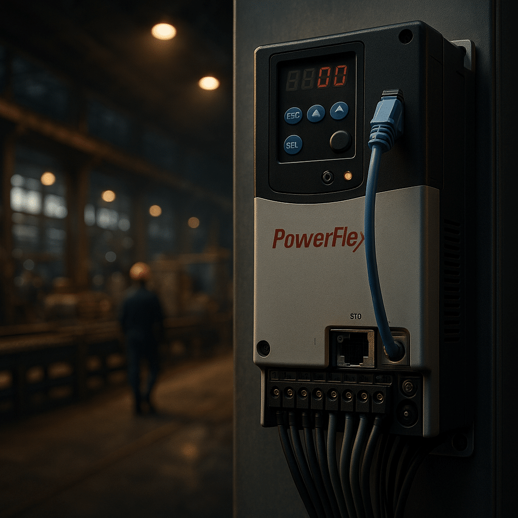
Allen Bradley Power Flex 525 VFD: Compact footprint, EtherNet/IP, and Safe Torque Off streamline commissioning.
Configuration, Safety, And Networking For The Rockwell PowerFlex 525
The drive arrives ready for networks. It provides an embedded EtherNet/IP port for cyclic control, diagnostics, and Automatic Device Configuration, so a replacement can inherit parameters from the PLC. Moreover, an RS‑485 port supports DSI and Modbus RTU for multidrop applications, which helps on cost‑sensitive retrofits. As for safety, dual‑channel STO meets SIL 2/PL d when wired correctly and removes gate signals to the output stage to prevent torque generation. In practice, the function integrates with an e‑stop or guard switch for a Category 0 stop. Furthermore, StepLogic sequences and an energy‑optimizer reduce PLC code on small machines and trim magnetizing current at light loads. Because the firmware also supports permanent‑magnet motors, users can leverage high‑efficiency designs without changing the platform. For manufacturer specifics, consult the official PowerFlex 525 specifications.
Practical Control Modes
V/Hz works for general‑purpose fans and pumps. However, sensorless vector control unlocks higher torque at low speed and faster recovery from load changes. Additionally, closed‑loop vector with an encoder improves speed regulation for indexing conveyors and extruders. As a result, builders can hold line speed within tight limits, even as viscosity or tension shifts. Moreover, the dual PID loops manage process feedback and trim setpoints without a separate controller. Consequently, integrators often map one loop to pressure while the second loop supervises temperature or provides cascade control. Finally, ride‑through features maintain operation during short sags by using the spinning motor as an energy source, and a “half‑bus” mode can continue reduced speed during deeper dips. For competitor context, compare Lenze’s i550 feature set on the i550 product page.
Maintenance And Lifecycle Tips
Plan for ventilation and dust control, then verify that heat‑sink fins stay clear. Additionally, keep a parameter backup on a laptop or secured server, and enable Automatic Device Configuration so a spare inherits the exact setup. Because electrolytic capacitors age, schedule a health check at the ten‑year mark or during major shutdowns. Moreover, check braking‑resistor wiring periodically and confirm the thermal contact is intact. For safety, test both STO channels during annual lockout validations and record the results. Finally, trend current, bus voltage, and fault codes from the PLC; early warnings reduce downtime and help target root causes. For a manufacturer contrast on longevity and microdrive design, see Eaton’s DM1 documentation (DM1 overview PDF) and Yaskawa’s GA500 details on the GA500 product page.
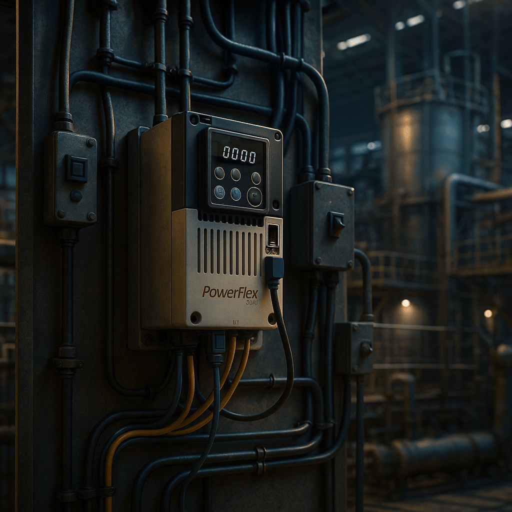
PowerFlex 525 installation essentials: input impedance, output filtering, and braking improve stability and uptime.
Product Recommendations And Sizing For The PowerFlex 520 Series
Start with motor full‑load current and duty class. Choose a Normal Duty size for variable‑torque loads, and select a Heavy Duty rating for conveyors, mixers, and lifts. Next, include input impedance for harmonic control, then specify an output load reactor or a dV/dt filter when motor leads exceed manufacturer guidance. Additionally, budget for a braking resistor when fast deceleration or vertical loads demand it. Because networking saves hours, standardize on EtherNet/IP where possible and reserve the RS‑485 port for simple multidrop retrofits. Finally, document parameter sets for different operating profiles so maintenance can swap recipes without hunting through the menu. To browse categories and accessories, start with core AC variable frequency drives, add input line reactors and output load reactors, and compare brands like ABB, Yaskawa, and Eaton.
Conclusion: When To Choose
Select this platform when you need a compact footprint, native EtherNet/IP, and integrated safety. It fits pumping, conveying, and light positioning duties while keeping commissioning simple. Moreover, the feature set rivals competitors such as Yaskawa GA500, ABB ACS580, Eaton DM1, and Lenze i550, yet the Logix integration often lowers lifecycle cost in Rockwell‑centric plants. If your application requires SIL 3 safety over network, consider the PowerFlex 527 or add external safety hardware. Otherwise, the PowerFlex 525 drive provides the right balance of capability, price, and serviceability for day‑to‑day production. For energy‑optimization tips that apply to this class of drives, review Rockwell’s article on evaluating motor and drive efficiency.
Read The Full Allen Bradley Power Flex 525 Research:
https://www.precision-elec.com/wp-content/uploads/2025/08/allen-bradley-power-flex-525-panel.png10241024Craig Chamberlinhttps://www.precision-elec.com/wp-content/uploads/2025/02/Precision-Electric-Logo-TEXT-ONLY-Color-NEW.pngCraig Chamberlin2025-08-31 09:01:002025-09-18 11:44:30Allen Bradley Power Flex 525 — Specs, Setup, And Best Uses
Plant managers, OEM engineers, and maintenance teams share a common goal: keep production flowing while reducing waste. A Yaskawa frequency drive makes that mission easier. The drive converts fixed utility power into a flexible, pulse‑width‑modulated output, so any standard AC motor can match real‑time process demands. Consequently, systems run only as fast as necessary, equipment lasts longer, and electricity bills shrink. Moreover, Yaskawa backs each unit with a century of R&D success and one of the lowest field‑failure rates in the industry, which means you install confidence—not risk—into every panel.
How a Yaskawa Frequency Drive Works
When three‑phase line power enters the rectifier, diode or IGBT bridges create a stable DC bus. Next, the inverter chops that bus into a variable‑frequency, variable‑voltage waveform that the motor perceives as clean three‑phase power. Therefore, speed is directly proportional to frequency, while advanced vector control maintains torque under load. Yaskawa embeds auto‑tuning routines that fingerprint motor inductance within sixty seconds, so technicians achieve two‑hundred‑percent starting torque without encoders.
Because dual microprocessors split real‑time current loops from diagnostics, the drive reacts to load changes in under two milliseconds. Safe Torque Off circuitry—certified to SIL3 and PL e—disconnects gate signals so the motor cannot generate torque during an emergency stop. These hardware details explain why engineers trust a Yaskawa frequency drive as the heart of their motion system.
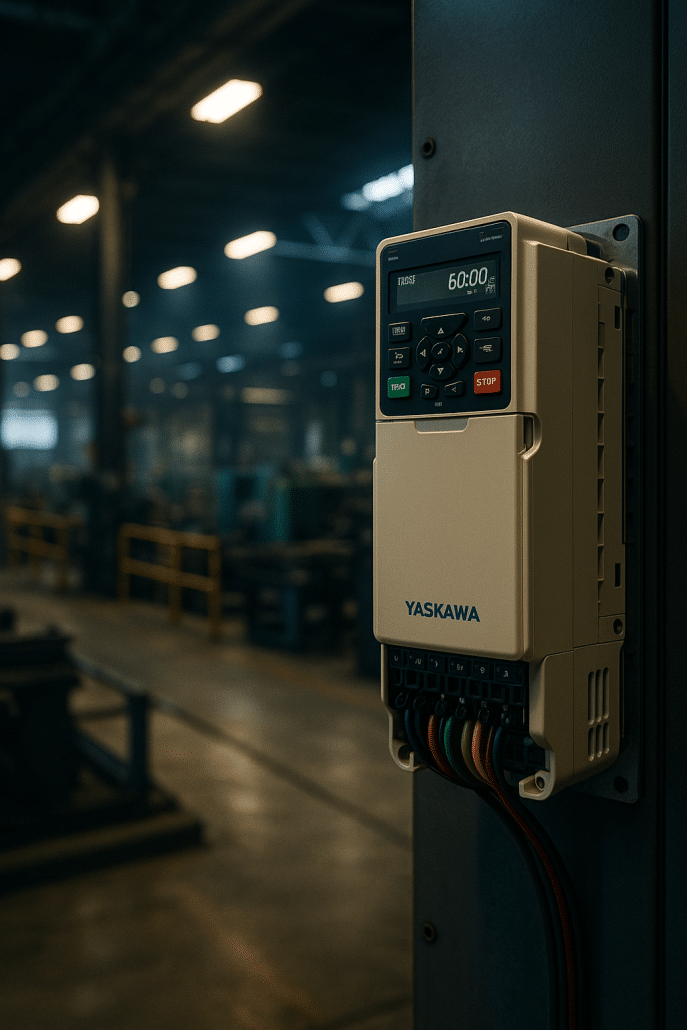
High‑efficiency yaskawa frequency drive GA800 in a rooftop air‑handler panel
Core Features and Industry Standards
Because uptime matters, every series of Yaskawa VFDs includes conformal‑coated boards, a speed‑search restart algorithm, and capacitor‑life monitors that warn long before failure. The electronics meet IEC 61800‑5‑1 safety and EN 61800‑3 EMC, while UL 61800‑5‑1 listing simplifies North‑American inspections. Furthermore, optional IP66 enclosures protect food‑processing lines. Communication cards support Modbus, EtherNet/IP, PROFINET, and EtherCAT, so the drive talks fluently to Rockwell, Siemens, or Beckhoff PLCs.
An intuitive LCD keypad matches parameter groups inside DriveWizard PC software, allowing you to clone setups via USB in seconds. For power‑quality compliance, the GA800 ships with a 3 % DC reactor already installed, and twelve‑pulse or eighteen‑pulse packages meet demanding IEEE 519 sites. If you need regeneration, the U1000 Matrix drive returns braking energy while drawing near‑sinusoidal input current. Competitors offer similar options; however, Yaskawa combines them in a compact footprint and backs them with global support.
Space‑saving GA500 Yaskawa variable frequency drive for OEM skids
Benefits and Real‑World Results
End users consistently record double‑digit savings. For instance, a Midwest grain facility replaced across‑the‑line conveyors with GA800 units and observed a forty‑two percent energy drop—enough to cancel a costly service‑entrance upgrade. Likewise, a Columbus water plant retrofitted booster pumps and logged a thirty percent reduction in kilowatt‑hours during the first year. Because the drives ramp smoothly, pipe hammer vanished and seal life doubled. In packaging, a plastics extruder tightened thickness tolerance and cut scrap by ten percent after switching to sensorless‑vector Yaskawa drives.
Beyond efficiency, the drives extend equipment life. Soft starts remove mechanical shock, while predictive counters track fan run time, internal temperature, and bus‑capacitor ripple, prompting service before failure. Consequently, a pulp‑and‑paper mill that swapped twenty legacy drives for new Yaskawa models saw unplanned downtime plummet by seventy‑six percent. These metrics prove that the right variable frequency drive delivers measurable value.
Choosing the Right Yaskawa Frequency Drive
Begin by matching motor horsepower and supply voltage. The GA800 handles constant‑torque loads up to 600 HP at 480 V, so crushers, mixers, and conveyors fit perfectly. For variable‑torque fans and pumps, the FP605 trims harmonics and offers embedded BACnet for building automation. OEM builders love the GA500; it reaches forty HP in a body smaller than a paperback. Need full regeneration?
As industries pursue ever‑higher efficiency and smarter automation, the ABB vfd has become a cornerstone of modern motor control. At its core, the ABB variable frequency drive adjusts the frequency and voltage supplied to an AC motor. Allowing precise speed regulation and significant energy savings. Because centrifugal loads such as pumps and fans obey the affinity laws. Reducing motor speed by only 20 percent can slash power use by roughly 50 percent.
Therefore, facility managers now regard variable‑speed control as low‑hanging fruit for both carbon‑reduction and cost‑reduction programmes. ABB has led the drives market for decades, yet many technicians still ask how an ABB solution stacks up against popular alternatives. This article explains why an ABB‑branded controller remains a safe, forward‑looking investment, outlines key specifications. It also compares competitive products, and shares real‑world performance data.
Why Choose ABB VFD Technology
First, ABB’s Direct Torque Control (DTC) algorithm delivers full motor torque in milliseconds without requiring an encoder. Consequently, machines such as extruders and winders gain lightning‑fast response while avoiding the complexity of feedback devices. Secondly, ABB embeds safety functions like Safe Torque Off (STO) to SIL 3 / PL e inside the drive. Eliminating external contactors and wiring.
Moreover, every modern ABB inverter ships with on‑board energy calculators that show live kilowatt savings directly on the keypad. The ABB vfd family also integrates DC chokes or active‑front‑end rectifiers that help users comply with IEEE 519 harmonic limits. Even ultra‑low‑harmonic variants achieve total harmonic distortion below five percent. For engineers who need proof, the ABB low‑voltage AC‑drives datasheet lists measured input‑current THD levels as low as three percent.
In addition, ABB’s “all‑compatible” platform unifies parameter‑menu structures from 0.25‑horse‑power micro‑drives up to multi‑megawatt common‑DC systems. Because the same PC tool—DriveComposer—or the DriveSize selection software covers the whole range. This allows technicians to face a gentler learning curve. Finally, global support centres in more than 100 countries ensure spare parts and field service remain. Available throughout a drive’s multi‑decade life‑cycle.
ABB VFD installation boosts pump energy efficiency.
ABB VFD Technical Specifications
Across the low‑voltage portfolio the power range spans 0.18 kW to 5 600 kW at 208–690 VAC. Medium‑voltage models extend ratings into the tens of megawatts. Output‑frequency capability typically covers 0–500 Hz, and many units allow 599 Hz for high‑speed spindles. When engineers select an ABB VFD drive, two duty classes are available. These include Normal Duty (110 percent overload for one minute) and Heavy Duty (150 percent overload for one minute). Ambient temperatures up to 40 °C require no derate, yet the drive can operate at 50 °C with additional fan assistance. Altitude correction factors begin above 1 000 m. To mitigate electromagnetic interference, EMC filters meeting IEC 61800‑3 categories C2 or C3 are factory‑installed. While ultra‑low‑harmonic active‑front‑end converters are offered for grids that demand THD < 5 percent.
Efficiency matters as well. According to the IEA‑4E VSD efficiency study, almost all modern variable‑speed drives already surpass the IE2 efficiency class defined in IEC 61800‑9‑2. Typical ABB losses stay 30–50 percent below the IE2 ceiling, translating to drive efficiencies around 97–98 percent at full load. Because less heat must leave the enclosure, panel builders can down‑size cooling hardware and reduce total installed cost.
ABB VFD vs Competitors
How does an abb vfd compare with other market leaders? Yaskawa’s GA800 series enjoys a reputation for legendary reliability, yet it lacks the built‑in harmonic mitigation found in many ABB AC drive models. Danfoss positions its VLT range squarely at HVAC, offering dedicated fire‑mode features that mirror ABB’s ACH 580. The Eaton PowerXL DG1 emphasises Active Energy Control, a voltage‑optimisation routine that adds two‑to‑ten percent extra savings, although ABB implements a comparable flux‑optimisation mode. Hitachi’s WJ200 drive boasts 200 percent torque at 0.3 Hz, yet ABB’s DTC can match that performance sensor‑lessly. Finally, Siemens SINAMICS shines in Totally Integrated Automation environments, whereas ABB remains protocol‑agnostic, supporting EtherNet/IP, PROFINET, Modbus TCP and many others.
Therefore, product selection often hinges on ecosystem fit, harmonic targets and service coverage. If a plant already runs ABB industrial robots, choosing an ABB speed controller reduces the spare‑parts catalogue and unifies engineering tools. Conversely, a facility dominated by Allen‑Bradley PLCs may prefer PowerFlex drives for tighter Studio 5000 integration. Nevertheless, many integrators deploy mixed fleets because modern drives share international standards such as IEC 61800‑5‑2 and UL 61800‑5‑1, ensuring basic interoperability.
Technician configuring ABB VFD for optimal motor control.
Real‑World ABB VFD Case Studies
A U.S. wastewater plant retrofitted its constant‑speed pumps with ABB VFD units and cut energy use by 30 percent. This energy cut is while halving peak demand. The independent evaluation published by the Columbus WWTF VFD case study shows specific energy dropping from 259 kWh / MG to 179 kWh / MG. Because the drives ramp the pumps gently, water hammer was reduced, lowering pipe failures. Similarly, a plastics extruder replaced an ageing DC drive with an ABB frequency converter. After implementation, they observed line‑speed variation shrink from ±2 percent to ±0.4 percent. Yielding a three‑percent scrap reduction. In mining, replacing across‑the‑line starters on a 2 MW conveyor with ABB medium‑voltage drives virtually eliminated belt slip and extended belt life by two years.
Even vertical transportation benefits. When a Midwest hospital installed regenerative ABB variable speed drives on its elevators. Also descending cars fed power back to the building, saving roughly 18 000 kWh per year. Meanwhile, crane operators at a Gulf‑Coast port reported smoother load control and faster cycle times. This is after migrating to ABB multi‑drive hoist packages.
Best Practices for ABB VFD Implementation
Proper sizing begins with accurate motor‑nameplate data. DriveSize software recommends an ABB AC drive that meets the true RMS current of the load profile. Next, observe cable‑length limits or specify dv/dt filters on long leads. Noise immunity depends on good grounding. So bond both ends of the motor‑cable shield to the drive frame and the motor housing. Furthermore, use shielded control wiring and route it away from power conductors. When regenerative braking energy cannot be reused, dimension dynamic‑brake resistors for the peak kinetic load.
Commissioning is equally critical. Always run the adaptive auto‑tune routine so DTC can model the motor precisely. Then, verify that STO wiring meets the required safety category. Finally, record baseline current, voltage and harmonics; these snapshots simplify future troubleshooting and support predictive‑maintenance initiatives.
Recommended ABB VFD Product Categories
Precision Electric stocks the full abb vfd range along with complementary technologies. For general‑purpose automation we suggest the ACS 580 in sizes to 500 kW—see our AC variable‑frequency‑drive catalogue. Heavy‑duty conveyors and grinders often require regenerative capability; in that case the modular ACS 880 fits, and our engineers can package it with input reactors and harmonic filters. When soft‑starting alone suffices, browse our soft‑starter selection. Additionally, if you must power a three‑phase ABB VFD drive from single‑phase supply, explore our rotary phase converters. For troubleshooting tips read our guides on over‑voltage faults, cooling issues, over‑current trips and our ground‑fault article.
Conclusion
The abb vfd remains a proven path to energy efficiency, process stability and equipment longevity. Because ABB combines advanced motor control, integrated safety and a vast power range, the drives deliver results across HVAC, water, manufacturing and heavy industry. By following recognised best practices and selecting the correct options, engineers can maximise ROI and future‑proof their installations.
Introduction: What A Danfoss Variable Frequency Drive Does
A danfoss variable frequency drive (VFD) adjusts motor speed and torque to match real process demand. Instead of running a motor at full speed and wasting energy with dampers or valves, the drive supplies only the frequency and voltage the load requires. Consequently, you lower kilowatt demand, reduce mechanical stress, and increase uptime. In practice, Danfoss combines robust hardware with intuitive software to make these outcomes repeatable. For product scope and documentation, see the official VLT® AutomationDrive FC 301/302 page and the educational primer What is a variable frequency drive?.
Moreover, the VLT AutomationDrive family covers a wide power range and supports induction, permanent‑magnet, and synchronous‑reluctance motors. As a result, you can standardize on one controller for many applications without locking into a specific motor brand. Additionally, features such as Automatic Motor Adaptation (AMA) and Automatic Energy Optimization (AEO) shorten commissioning and capture extra efficiency at partial load. Importantly, Danfoss emphasizes power quality and reliability: most models ship with integrated DC‑link chokes and RFI filters to curb harmonics and electromagnetic emissions.
Furthermore, rugged options such as conformal coating, high ambient temperature ratings, and back‑channel cooling help the electronics survive harsh conditions. Finally, when you pair a danfoss variable frequency drive with inverter‑duty motors and sound installation practices, you protect the entire system—from breakers and transformers to bearings and seals.
Why Variable Speed Saves Energy In Pumps And Fans
Variable speed saves energy because many loads follow the fan and pump affinity laws. In short, the power required changes roughly with the cube of speed. Consequently, trimming speed by 20% can cut power by ~50% on a centrifugal blower. Likewise, turning down a pump from 60 Hz to 48 Hz often delivers the same flow with dramatically less input power. Therefore, a danfoss variable frequency drive usually pays for itself quickly in air‑handling units, cooling towers, process pumps, and conveyance fans.
However, energy efficiency is only one benefit. Because a Danfoss AC drive ramps smoothly, it eliminates across‑the‑line inrush and reduces belt slip, water hammer, and pressure spikes. Moreover, built‑in PID control lets the drive hold setpoints for pressure, flow, or temperature without extra controllers. Additionally, sleep/wake functions prevent dead‑heading and idle run time on pump systems. In many facilities, these control features extend mean time between failures and reduce maintenance callouts.
For planning, you should also consider monitoring features. Danfoss provides energy readouts, fault histories, and condition‑based monitoring options so teams can see savings and spot degrading performance early. In the same way, network options—PROFINET, EtherNet/IP, BACnet, and Modbus—simplify integration with existing PLC and BAS systems. For selection help or a quote, review our AC Variable Frequency Drives category.
Danfoss variable frequency drive energy-saving for fan and pump systems
Harmonics, EMC And Standards Compliance
Nonlinear loads, including any danfoss variable frequency drive, draw current in pulses and can inject harmonics into the supply. Therefore, designers reference IEEE 519‑2014 when setting distortion targets at the point of common coupling. In parallel, EMC immunity and emission requirements fall under IEC 61800‑3 for adjustable‑speed drives. Because motor insulation sees fast voltage rise times, NEMA MG 1 Part 31 defines inverter‑duty criteria so motors survive high dv/dt and reflected‑wave peaks on long leads.
To meet these expectations, Danfoss integrates DC‑link chokes and RFI filters as standard on many frames. Consequently, total harmonic current distortion often drops into acceptable ranges without external filters. Furthermore, dedicated low‑harmonic or active front‑end options cancel most remaining harmonic content when utility or generator constraints are tight. Additionally, output dV/dt or sine‑wave filters keep motor terminal voltage within insulation limits, which protects older motors when retrofitting a drive. For practical selection and troubleshooting, see our cornerstone guides on VFD overvoltage on decel, VFD overcurrent, and VFD overheating.
In practice, follow a simple rule set. First, verify short‑circuit ratings, protective device coordination, and enclosure ingress ratings for the site. Second, select cable types approved for VFD outputs and land shields correctly at one end to avoid ground loops. Third, apply line reactors or passive filters when supply impedance is very low, and specify inverter‑duty motors or output filters when cable runs are long. Finally, document the target THD and EMC class so commissioning can confirm compliance. If you need components, explore input line reactors and output load reactors.
INSTALLATION AND COMMISSIONING BEST PRACTICES
Successful projects start with practical details. Begin with a load profile and a realistic minimum speed. Then size the danfoss variable frequency drive for continuous current with the correct overload class for the duty cycle. Next, match the enclosure rating to the environment and plan heat removal; Danfoss back‑channel cooling can eject most waste heat through a duct, which reduces cabinet temperature and improves service life. During commissioning, use Automatic Motor Adaptation to identify motor parameters and enable Automatic Energy Optimization for part‑load savings.
Moreover, program PID, sleep, and minimum‑flow protections before turnover. Additionally, verify digital and analog I/O, fieldbus addresses, and safety circuits such as Safe Torque Off. Because issues often trace to wiring, confirm control commons, shield terminations, and analog scaling before starting a formal autotune. For a step‑by‑step setup overview, review our guide to VFD autotune and our checklist for VFD won’t start—control wiring errors.
For reliability, add the right accessories. Input line reactors mitigate transients and lower harmonic currents when upstream impedance is weak. Output load reactors or dV/dt filters reduce motor stress on long cable runs. Finally, establish a spare‑parts plan that includes a compatible keypad, cooling fans, and a preconfigured spare drive. Consequently, you can swap hardware in minutes while the failed unit goes to repair without extending downtime. If you maintain legacy systems, consider our soft starter and VFD phase converter categories for special use cases.
Danfoss variable frequency drive energy‑saving
Product Recommendations For Common Scenarios
Because needs vary, match features to the job rather than chasing the highest spec sheet. For general industrial machinery and conveyors, a danfoss variable frequency drive with the VLT AutomationDrive FC 302 feature set covers induction and permanent‑magnet motors with sensorless vector control and integrated safety. For building HVAC, choose a Danfoss AC drive with multi‑pump control and BACnet to simplify air and water balancing. Meanwhile, water and wastewater sites benefit from anti‑cavitation and anti‑ragging functions and rugged enclosures. When you are ready to buy, start with our curated Danfoss and multi‑brand VFD catalog.
When multi‑brand comparisons help, evaluate peers on the same criteria. For instance, Yaskawa’s GA800 general‑purpose drive offers broad horsepower coverage and straightforward setup; however, value remains similar when sized and installed with the same best practices. Likewise, ABB highlights the high cost of unplanned downtime—its global survey reports a typical $125,000 per hour impact—which reinforces the case for reliable drives and proactive maintenance (ABB press release). Therefore, base your shortlist on local support, lead time, and accessories as much as on raw performance.
To streamline procurement and maintenance, standardize a core set of frame sizes and option codes across your plant. Additionally, select complementary accessories—line reactors, output reactors, and configured packages—from a consistent supplier. As a result, technicians learn one interface, spares fit multiple assets, and inventory stays lean. Finally, document parameter templates for common motors so replacements restore operation fast and repeatably.
Conclusion: Selecting A Danfoss Variable Frequency Drive
A danfoss variable frequency drive delivers measurable energy savings, tighter process control, and gentler mechanical dynamics. However, the best outcomes come from matching features to the duty, wiring and filtering to the site, and commissioning to the plan. Therefore, treat the drive, motor, and power system as one unit and verify each choice against standards and the environment. In practice, Danfoss combines efficient thermal design, integrated power‑quality hardware, and broad motor compatibility into a dependable platform.
Moreover, the ecosystem of software, option cards, and service support makes scaling from small fans to large process pumps straightforward. Consequently, organizations that standardize on a Danfoss VFD family reduce energy use and downtime while improving safety and compliance. If you need help selecting, sizing, or commissioning, our engineering team can translate requirements into a configured bill of materials and a reliable startup plan.
Read The Full Danfoss Variable Frequency Drive Research:
Variable Frequency Drives (VFD) have become a cornerstone of modern motor control because they let an AC motor run only as fast as the job requires. In a typical plant, motors consume roughly two‑thirds of the electricity, yet many still operate at full speed behind throttling valves or dampers. By installing a VFD — also called a variable speed drive, adjustable‑speed drive, AC drive or frequency inverter — engineers turn that wasted energy into measurable savings while gaining far better process control.
Consequently, organisations ranging from municipal water utilities to high‑speed packaging OEMs are retrofitting pumps, fans and conveyors with drives to shave 20‑50 % off energy bills. At the same time, soft‑starting eliminates damaging inrush currents and mechanical shock, extending equipment life. Add diagnostics, predictive maintenance data and functional‑safety options such as Safe Torque Off (STO), and the business case becomes compelling.
This guide distills manufacturer documentation, peer‑reviewed studies and industry standards into practical advice: why speed control saves money, which specifications matter, how to comply with IEC 61800 and IEEE 519, and which general‑purpose drives from ABB, Yaskawa, Eaton, Lenze and others stand out in 2025.
VFD energy‑savings curve versus speed
Why VFD Speed Control Slashes Operating Costs
A centrifugal fan or pump follows the affinity laws: power varies with the cube of speed. Therefore, cutting speed by just 20 % can halve power draw. A Midwest water plant that swapped constant‑speed pumps for drive‑controlled units reduced specific energy from 259 kWh/MG to 179 kWh/MG and halved peak demand. For a deeper explanation of these affinity‑law relationships, read our Variable Frequency Drive Basics guide. Those numbers echo the 52 % blower‑energy drop achieved across 78 retail stores after an HVAC retrofit that slowed fans during unoccupied hours.
Beyond energy, speed control stabilises processes. With electronic flow modulation, valves stay fully open, eliminating throttling losses and cavitation. Consequently, wear on seals, impellers and belts falls, maintenance intervals stretch, and vibration‑related downtime declines. Diagnostics in today’s smart controller warn operators of overload, under‑load or over‑temperature, enabling proactive repairs.
Traditional across‑the‑line starting demands 600 % rated current, causing voltage sags and utility penalties. Conversely, the drive ramps from 0 Hz with only rated current, which further reduces demand charges. Because torque shock disappears, conveyor belts no longer jerk and couplings last longer. Ultimately, variable speed drives convert an energy project into a reliability upgrade — a double win for any maintenance budget.
Inside a VFD — Key Components and Specifications
A modern drive is a power‑electronics sandwich: a three‑phase rectifier, a DC‑link with smoothing capacitors plus inductors, and an IGBT inverter that switches thousands of times per second to synthesise a new AC waveform. The control board orchestrates PWM patterns while keeping a constant Volts‑per‑Hertz ratio so the motor delivers torque at any speed. Critical specifications include voltage/power range, overload rating, efficiency class, harmonic mitigation and safety options:
Voltage & power range. Low‑voltage drives cover 0.75 kW to 500 kW; medium‑voltage units reach multi‑megawatt capacities.
Overload rating. Verify heavy‑duty (150 % for 60 s) versus normal‑duty capability; Eaton’s DG1 meets the former.
Efficiency class. Per IEC 61800‑9‑2, IE2 drives hit 97–98 % full‑load efficiency.
Harmonic mitigation. DC chokes or 12‑pulse rectifiers help meet IEEE 519 limits.
Safety options. STO certified to SIL 3 is standard on ABB ACS580 and Yaskawa GA800 families.
Because the inverter output is a rapid PWM waveform, reflected‑wave over‑voltage can exceed 1600 V at the motor terminals. Hence, NEMA MG1 Part 31 inverter‑duty motors or dv/dt filters are recommended on long cable runs. The same high rise‑time causes bearing currents; installing AEGIS® grounding rings or insulated bearings prevents premature failure. Finally, heat dissipation (≈3 % of motor power) dictates panel cooling; always derate above 50 °C or at altitudes above 1000 m.
Standards, Compliance and Installation Best Practices
Meeting the right standards is not paperwork — it is insurance against nuisance trips and safety incidents. First, select drives tested to UL 61800‑5‑1 and CE‑marked. Second, design harmonic mitigation to the IEEE 519‑2014 guideline; many utilities insist on ≤5 % voltage THD at the point of common coupling. Third, specify cabling that meets NEMA MG1 Part 31 insulation requirements.
Grounding and shielding matter just as much. For wiring examples see our AC drive troubleshooting article. Always route motor conductors and protective earth together in a metallic conduit or use a shielded VFD cable. Moreover, bond the shield 360° at both ends and connect the drive frame to the panel back‑plate with a low‑impedance strap.
Integrate the drive’s Safe Torque Off into the E‑stop loop and validate to ISO 13849‑1 (PLe). Drives such as the Lenze i550 or Rockwell PowerFlex include internal brake choppers; pairing them with the correct resistor avoids over‑voltage trips on fast stops. During commissioning run the autotune, set the electronic thermal overload to nameplate amps and program skip frequencies to dodge resonant speeds. Finally, document parameters in your CMMS and keep cloud backups.
Real‑World Results — From Baseline to Outcome
The most convincing proof of value comes from measured data:
Municipal wastewater. Two 125 HP pumps retrofitted with ABB ACS580 drives cut daily energy from 820 kWh to 470 kWh (‑43 %) and lengthened blower maintenance from 9 months to 15 months.
Food‑processing conveyor line. A Yaskawa GA800 replaced starters on four 10 HP motors, eliminating gearbox failures and reducing peak current from 420 A to 100 A, saving $7 000 annually.
Commercial HVAC. Eaton DG1 drives with pressure‑reset logic cut pump energy 48 % and fan energy 36 %, achieving an 18‑month payback.
Therefore, energy savings routinely offset capital cost in under two years, while reduced parts inventory, quieter operation and fewer nuisance trips amplify ROI.
Comparing leading VFD product families
Top Industrial VFD Lines and How to Choose
ABB ACS580. Delivers DTC torque control, embedded STO and a Bluetooth assistant. Full specs.
Yaskawa GA800. Runs induction, PM and SynRM motors without an encoder, provides web‑server diagnostics and meets IE2 efficiency. GA800 details.
Eaton PowerXL DG1. Features a 5 % DC choke, EMI filter and Active Energy Control algorithm. DG1 catalog.
Lenze i550. Compact, modular and available to 132 kW in IP20, 55 or 66. i550 options.
When selecting a drive, begin with motor FLA and overload needs, then filter by environment, communication bus and harmonic strategy. Next, compare life‑cycle tools: ABB DriveComposer, Yaskawa DriveWizard and Eaton Power Xpert Gateway streamline setup and monitoring.
Implementing a drive is one of the fastest, lowest‑risk ways to cut energy use, elevate process precision and extend equipment life. By combining solid specifications, compliance with UL 61800 and IEEE 519, and the installation practices outlined above, your team can replicate the impressive savings documented here. Modern units add IIoT connectivity and predictive diagnostics, so the benefits grow over time.
Remember that an inverter‑duty motor, shielded cable and proper grounding are essential companions to any controller. Equally important is commissioning: a five‑minute autotune sets the stage for years of reliable operation, while parameter backups reduce future downtime to minutes.
If you need help selecting, programming or troubleshooting equipment — or simply want to verify that your existing fleet is optimised — contact Precision Electric today. Our in‑house engineers and UL 508A panel shop deliver turnkey solutions from single‑drive retrofits to multi‑axis systems. Therefore, leverage the research below and start identifying motors that still run wide open when they could be sipping power through the right controller.
The allen bradley powerflex 525 is a compact, networked AC variable frequency drive built for dependable machine control. Additionally, the PowerFlex 520 Series spans 0.5–30 HP and 100–600 V input classes for global use. Moreover, embedded EtherNet/IP, a USB port for offline configuration, and Safe Torque Off simplify commissioning and safety validation. For authoritative specifications and certifications, review the PowerFlex 525 product page and the PowerFlex 520‑Series technical data. Furthermore, the Rockwell press release details the modular control and power cores and MainsFree USB setup. Therefore, machine builders standardize on one footprint while supporting open‑loop and closed‑loop modes. Besides energy benefits, sensorless vector control improves low‑speed torque and speed stability. Consequently, users deploy the drive on conveyors, pumps, blowers, and mixers with consistent results.
However, engineering decisions should consider ambient temperature, enclosure airflow, and derating rules. Additionally, the allen bradley powerflex 525 operates to 50 °C without derating and supports fan kits for hotter panels. Moreover, a built‑in dynamic brake transistor supports quick, predictable stops with a sized resistor. In addition, internal EMI filtering and a pre‑charge circuit protect upstream equipment and minimize inrush. Likewise, removable MOV grounding jumpers allow operation on ungrounded or high‑resistance systems. As a result, plants can adopt this compact VFD broadly while meeting site power‑quality constraints.
Introduction Quick Facts
Power range: 0.5–30 HP; input classes: 100–600 V.
Embedded EtherNet/IP, USB offline setup, and Safe Torque Off.
Applications: conveyors, pumps, fans, blowers, and mixers. :contentReference[oaicite:2]{index=2}
Controls, Safety, And Networking In PowerFlex 525
Engineers choose the powerflex 525 because it delivers strong control with minimal complexity. Additionally, teams start in V/Hz for simple loads, then enable sensorless vector when regulation tightens. However, an optional encoder enables closed‑loop velocity control where precision matters. Furthermore, two PID loops support process control without an external controller in many cases. Consequently, technicians can hold pressure, level, or tension directly from the drive. For networking, every unit ships with EtherNet/IP, so a PLC treats the PF525 like any other node.
Moreover, RS‑485 with Modbus‑RTU eases migrations from legacy serial systems. Similarly, zero‑stacking saves panel width up to 45 °C while retaining service access. In addition, conformal coating and robust thermal design support demanding shop floors. For ratings, overload classes, and EMC categories, consult the PowerFlex 520‑Series technical data before finalizing the panel. Therefore, the allen bradley powerflex 525 suits machine builders who value predictable setup and service.
Allen Bradley PowerFlex 525: compact EtherNet/IP drive with STO and USB.
Energy performance often decides the business case for a retrofit. Therefore, centrifugal loads benefit most, because power roughly scales with the cube of speed. As the peer‑reviewed pump study shows, dropping pump speed by 10% produced about 30% less energy use. Additionally, permanent‑magnet motor support and an economizer mode deepen part‑load savings. Moreover, Precision Electric recommends staged tuning using our VFD autotune steps to maximize efficiency.
Likewise, the Marlen case study documents a food‑processing OEM capturing roughly 40% energy savings. Furthermore, the project improved portion accuracy and simplified maintenance compared with hydraulics. In parallel, the VFD programming guide helps teams pre‑configure parameters via USB for faster startup. Consequently, the rockwell powerflex 525 often pays back through lower energy, smoother starts, and fewer mechanical shocks. Finally, plants also report quieter operation because higher switching frequencies reduce audible noise.
Troubleshooting And Commissioning For PowerFlex 520 Series
Reliable commissioning prevents nuisance downtime and support calls. First, enter exact nameplate data and run an auto‑tune to tighten torque models. Next, verify I/O polarity, since the EtherNet/IP drive accepts sink or source inputs at 24 V DC. Additionally, separate control wiring from motor leads and bond shields at both ends. When long leads are unavoidable, select input line reactors or output load reactors to limit reflected‑wave stress. Consequently, motor insulation and bearings experience less electrical stress over time.
If acceleration trips on overload, follow our overcurrent fault troubleshooting to correct the current limit or ramp. Moreover, confirm the MOV jumper before operating on ungrounded systems to avoid nuisance faults. For safety, route emergency stops through the STO channels rather than removing mains power. Afterward, validate the safety function and document the parameter set for recoveries. Therefore, technicians can restore a spare module quickly and reduce mean‑time‑to‑repair.
Product Recommendations And Compatible Alternatives
Project constraints vary, so a short bill of materials helps engineers move fast. For harsh or noisy mains, pair the allen bradley powerflex 525 with input line reactors. For long runs or high switching frequencies, add output load reactors at the motor to soften dv/dt. If the site requires three‑phase from single‑phase, our VFD phase converters maintain full speed control. Additionally, plan enclosure airflow early so thermal derating does not surprise the schedule.
However, some standards or corporate preferences require different brands in the same class. In those cases, evaluate ABB ACS580 or Yaskawa GA500 units; our ABB drive catalog and Yaskawa drive catalog pages show current options. Nevertheless, many facilities prefer tight Logix integration and consistent tooling across machines. As a result, the AB PowerFlex 525 remains a strong default for OEM builds and retrofits alike. When a legacy unit goes end‑of‑life, use our VFD replacement guide to plan the swap and testing.
PowerFlex 525 Installation: wiring, STO, and tuning essentials.
Conclusion And Next Steps
The operational sweet spot for this platform is broad across conveyors, mixers, blowers, and pumps. Because it supports V/Hz, vector, and closed‑loop modes, teams can standardize hardware without sacrificing performance. Additionally, consistent I/O, safety, and networking lower training time for cross‑functional crews. Therefore, organizations deliver more machines with fewer surprises and faster ramp‑ups.
Finally, apply sound wiring, grounding, and thermal practices, then record the configuration for repeatability. Afterward, monitor trends and alarms to guide predictive maintenance and fine‑tune setpoints. When you need help turning specifications into a working bill of materials, Precision Electric can assist with sizing, startup, and training. In summary, the allen bradley powerflex 525 offers dependable control in a compact package.
Read The Full Allen Bradley Powerflex 525 Research:
Yaskawa VFD drives power millions of motors worldwide. By transforming fixed‑frequency utility power into a precisely modulated voltage and frequency, they let engineers dial in the exact speed and torque a process needs. The results are immediate: lower energy bills, longer equipment life, and rock‑solid process control. Because every plant manager wants more output for less cost, demand for Yaskawa VFD drives and comparable variable speed drives has soared. Yaskawa, founded in 1915, focuses almost solely on motion control, and that specialization shows in products that boast a mean time between failures (MTBF) of 28 years. In this guide you will learn why these drives excel, how they compare with other brands, and what steps ensure a flawless installation.
Energy Efficiency Gains
Idle valves, dampers and throttling rings waste electricity because centrifugal loads obey the cube law: halve the speed and you slice power by almost 90 %. A Border States Electric case study proved the math when a municipal pump station cut annual consumption by 30 % after installing Yaskawa GA500 inverters. Every model in the current Yaskawa line includes an automatic energy optimisation mode that trims output voltage as load decreases, squeezing an extra 5–8 % from already impressive savings. Furthermore, the U1000 matrix drive returns regenerative energy to the grid, eliminating braking resistors and meeting IEEE 519 harmonic limits. Together, these features make Yaskawa VFD drives a cornerstone of any corporate sustainability plan.
Competitors offer similar promises, yet measured data often favours Yaskawa. A grain facility in the Midwest swapped aged across‑the‑line starters for Eaton PowerXL DG1 drives and enjoyed a 42 % reduction in conveyor energy. However, when an identical conveyor later received a GA800, the site logged an additional 6 % cut because the Yaskawa unit’s adaptive flux control lowered magnetising current at partial loads. Although savings vary by application, engineers repeatedly confirm that Yaskawa’s long experience with vector algorithms pays tangible dividends.
Energy savings with Yaskawa VFD drives
Yaskawa VFD Reliability Improvements
Downtime destroys profitability, so reliability ranks high when specifying a variable frequency drive. Yaskawa coats every printed circuit board with moisture‑blocking resin, rates DC bus capacitors for 10 000 h at 105 °C, and tests terminals to stringent vibration levels. These design choices translate into exceptional field results. A southern pulp mill replaced twenty 1990‑era drives with GA800 units. Over the following twelve months, unplanned drive trips fell by 76 % while maintenance labour dropped by 120 hours. Similar stories appear in ABB white papers, yet Yaskawa’s published 245 000‑hour MTBF stands among the highest in the industry. Because parts are stocked worldwide by partners such as Precision Electric’s VFD repair center, users also enjoy fast support.
Reliability includes data transparency. The GA500 and GA800 log the last ten faults with date stamps, fan runtime, remaining capacitor life and peak current. Technicians download this information through DriveWizard software, identify root causes and schedule proactive maintenance—no guesswork, no unnecessary shutdowns. Competitors such as Hitachi WJ200 and Eaton DG1 record fewer parameters, making Yaskawa’s diagnostic depth a decisive advantage for plants that run 24 × 7.
Precision Process Control
Energy and uptime matter, yet product quality often influences revenue even more. Yaskawa VFD technology employs high‑resolution current vector control that maintains speed within ±0.01 % without an encoder. After an Ohio extrusion line upgraded to GA500 drives, film thickness variation tightened from 18 µm to 5 µm and scrap fell by 12 %. Should an application demand ultimate accuracy—crane hoists, elevators or test stands—the same drives accept encoder feedback and shift into closed‑loop vector mode. Meanwhile, intuitive autotuning reads motor constants in less than a minute, which means engineers can reach specification faster than with many rival brands.
Process integration is equally polished. The GA800 ships with dual‑port EtherNet/IP and Modbus TCP, enabling Device‑Level Ring topologies without external switches. PROFINET, PROFIBUS, BACnet and CAN Open cards slide into the option slot in seconds. For HVAC retrofits, the HV600 model adds embedded fire‑mode logic and BAS macros. Because connectivity arrives out of the box, integrators finish projects sooner and avoid hidden accessory costs.
Yaskawa VFD Product Recommendations
Model selection starts with the load, yet knowing Yaskawa’s flagship offerings streamlines any project quotation.
GA500 Micro Drive
The GA500 spans 1⁄8 HP to 40 HP. It measures just 84 mm wide in smaller ratings yet delivers dual Safe Torque Off inputs certified SIL3 / PL e. Bluetooth commissioning slashes panel time, and single‑phase 240 V input creates three‑phase output—ideal for rural pumps. For purchasing, visit our Yaskawa drives catalog.
GA800 Industrial Drive
Up to 600 HP at 480 V, the GA800 operates induction, permanent‑magnet and synchronous‑reluctance motors with identical firmware. A vivid multi‑line display, built‑in applications wizard and conformal coating make it the workhorse for harsh environments. Compare it with the Eaton PowerXL DG1; you will notice Yaskawa’s menu structure is quicker to learn.
U1000 Matrix Drive
Regenerative loads such as downhill conveyors waste energy unless the system can push power back to the grid. The U1000’s direct AC‑to‑AC matrix topology achieves <3 % THD and >0.98 power factor while returning energy, meeting strict utility requirements without extra active filters. For specifications see the official product page. Precision Electric also stocks alternatives like ABB ACS580 and Hitachi WJ200 when lead time is critical.
GA500 industrial model installed
Best Practices for Implementation of Yaskawa Variable Frequency Drives
Correct Sizing & Selection
Select Normal‑Duty ratings for centrifugal loads and Heavy‑Duty ratings for positive‑displacement pumps or crushers. Verify that overload current equals at least 120 % for 60 s, in line with NEMA MG‑1. Additionally, match carrier frequency to the motor insulation class to balance efficiency and audible noise.
Installation Essentials
Bond the drive to the protective earth bar with a short, wide strap. Use shielded VFD cable and add a three‑percent line reactor on units ≤ 25 HP to cut harmonics. Where motor leads exceed 50 m, install a dV/dt filter to protect winding insulation. Yaskawa supplies bolt‑on reactors that preserve enclosure space.
Maintenance & Firmware
Plan an annual shutdown to vacuum heatsinks and read the on‑board “remaining life” counters for capacitors and fans. Use DriveWizard to archive parameters before firmware updates. Keep one pre‑programmed spare for every ten critical drives; a Midwest bottling plant avoided $40 000 in lost production by hot‑swapping a GA500 in ten minutes. Should you need expert help, our Yaskawa service page lists available field services.
Conclusion on Yaskawa VFDs
Yaskawa VFD drives blend efficiency, resilience and precision inside an easy‑to‑use package. Their 28‑year MTBF, global parts availability and wizard‑driven setup distinguish them from otherwise capable rivals. Whether you manage HVAC fans, water pumps or extrusion lines, choosing Yaskawa’s variable frequency technology will cut energy costs, stabilise quality and extend motor life.
In industrial applications, achieving precise three phase motor speed control is crucial for process efficiency and equipment longevity. A 3 phase motor VFD, or Variable Frequency Drive, is a power conversion device that accomplishes this by taking a fixed frequency and voltage AC power source and converting it into a variable frequency and voltage output. As detailed in documentation from manuals.plus, this allows the VFD to precisely regulate the rotational speed of a connected AC induction motor. Consequently, the drive can match the motor’s output to the exact demands of the load, offering a level of control that is impossible with a direct-on-line motor starter. You will also see these devices referred to as an AC motor drive, an adjustable frequency drive, or a 3 phase inverter.
3 Phase Motor VFD: Energy Savings & Soft Start
Beyond basic speed regulation, the primary reason for implementing a VFD is the significant potential for energy savings, particularly with variable torque loads like fans and pumps. For instance, the U.S. Department of Energy highlights that a VFD can drastically reduce input power requirements; in fact, a 20% reduction in motor speed can result in energy savings of nearly 50%, according to U.S. Department of Energy. Furthermore, VFDs provide soft-starting capabilities, which gradually ramp up the motor’s speed. This process significantly reduces the mechanical shock and electrical inrush current associated with across-the-line starts, thereby extending the life of motors, belts, gears, and bearings.
The versatility of a VFD setup makes it indispensable across countless industries, including manufacturing, HVAC, and water treatment. By providing smooth, stepless control, these drives improve process quality, reduce operational noise, and minimize equipment wear and tear. While there are some technical considerations to be aware of, as noted by Ori-ental Motor Blog, the operational benefits are substantial. In other words, integrating a VFD offers a powerful solution for optimizing system performance, reducing energy consumption, and lowering long-term maintenance costs for nearly any application involving a three-phase motor.
Fundamental Operating Principles: How a VFD Works for 3 Phase Motor Speed Control
At its core, a Variable Frequency Drive (VFD) provides precise three phase motor speed control by altering the electrical power supplied to the motor. A vfd for 3 phase motor fundamentally operates by taking standard, fixed-frequency AC power and converting it into a variable-frequency, variable-voltage output. In other words, this allows the ac motor drive to precisely dictate the rotational speed of the motor shaft. This process not only enables speed regulation but, as noted by U.S. Department of Energy, also offers significant energy savings and reduced mechanical stress on equipment.
The answer to “how a VFD works” lies in a three-stage power conversion process. Initially, a rectifier circuit converts the incoming AC supply into pulsating DC voltage. Following this, the DC bus, which consists of large capacitors, smooths out these pulsations to create a stable, high-voltage DC supply. For instance, a 480V AC supply can be converted to a 650-680V DC bus, as explained in technical documentation from manuals.plus. These first two stages prepare the power for the final and most critical step.
Finally, the inverter stage takes over, functioning as a sophisticated 3 phase inverter. This section uses high-speed transistors, typically Insulated Gate Bi-polar Transistors (IGBTs), to chop up the DC voltage. By switching these IGBTs on and off rapidly using a technique called Pulse Width Modulation (PWM), the VFD creates a simulated three-phase AC sine wave at any desired frequency. As detailed by Precision Electric AC Motor Speed Control Manual, it is by controlling this output frequency that the drive directly controls the motor’s speed, making it a highly effective motor speed controller.
A Variable Frequency Drive (VFD) is essential for precise three phase motor speed control, allowing for optimized performance and energy efficiency in industrial applications.
Critical VFD Sizing and Selection Criteria
Selecting the correct VFD for 3 phase motor applications requires a more detailed analysis than simply matching horsepower. The most critical parameter is the motor’s Full Load Amps (FLA), which is always listed on the motor nameplate. Therefore, you must ensure the VFD’s continuous amperage rating meets or exceeds the motor’s FLA rating. For some applications, it is also necessary to oversize the drive; for instance, a VFD may need to be derated when running a three-phase motor on a single-phase power source, as noted by documentation from Precision Electric AC Motor Speed Control Manual. Always consult the VFD manufacturer’s specifications for guidance on these adjustments.
Furthermore, the application’s load type is a decisive factor for achieving effective three phase motor speed control. Loads are typically categorized as either variable torque or constant torque. Variable torque loads, such as centrifugal pumps and fans, require significantly less torque at lower speeds. In fact, a U.S. Department of Energy rule of thumb states that reducing fan speed by 20% can cut input power by about half, according to Precision Electric AC Motor Speed Control Manual. In contrast, constant torque loads like conveyors and positive displacement pumps require the VFD to provide near-full torque across the entire speed range, thus demanding a more robust drive.
Finally, you must consider the operating environment and the available input power. Ambient temperature, altitude, and the presence of dust or moisture directly impact VFD performance and lifespan, dictating the required NEMA enclosure type for protection. In addition, properly sizing a drive requires factoring in current distribution and other electrical characteristics of the system, as highlighted by resources from KEB America Blog. Overlooking these criteria can lead to premature drive failure, motor damage, and costly operational downtime.
Matching the VFD for 3 Phase Motor to Your Load Type
Selecting the correct VFD for a 3 phase motor requires a thorough understanding of the mechanical load it will be driving. In general, loads are categorized into two primary types: variable torque and constant torque, each demanding different performance characteristics from the ac motor drive. Consequently, mismatching the drive to the load type can lead to inefficient operation, nuisance tripping, or even damage to the motor or the VFD itself. Therefore, a careful analysis of the application’s torque-speed requirements is the foundational step in proper VFD selection and setup.
How 3 Phase Motor VFD Save Energy
Variable torque loads, such as centrifugal pumps and fans, are the most common applications for three phase motor speed control and offer the greatest potential for energy savings. For these systems, the torque required is proportional to the square of the speed, while the horsepower is proportional to the cube of the speed. According to U.S. Department of Energy, this principle, known as the affinity laws, means that even a small reduction in motor speed can yield significant power reduction. For instance, as noted by Precision Electric AC Motor Speed Control Manual, reducing fan speed by 20% can cut energy consumption by nearly 50%. VFDs designed for variable torque loads are often rated as “Normal Duty” and are sized closely to the motor’s Full Load Amps (FLA).
In contrast, constant torque loads demand a consistent level of torque from the motor, regardless of its operating speed. Prime examples include conveyors, extruders, positive displacement pumps, and machine tool spindles. These applications require the motor to produce full torque even at very low speeds, which places a high demand on the VFD, especially during startup. As a result, VFDs for these applications must be robust and are often referred to as “Heavy Duty” drives. They are typically oversized to handle the high starting currents and continuous thermal load without tripping. As detailed in technical documentation from Precision Electric AC Motor Speed Control Manual, selecting a Heavy Duty rated drive ensures reliable performance under these demanding conditions.
This diagram illustrates the core stages of a VFD, converting incoming AC power to DC and then back to a variable frequency AC output. This process allows for precise three phase motor speed control.
Essential Guide to Variable Frequency Drive Wiring
Proper variable frequency drive wiring is fundamental to the safety, performance, and reliability of any 3 phase motor VFD installation. Before beginning any work, it is absolutely critical to follow strict Lockout/Tagout (LOTO) procedures to ensure all sources of power are de-energized and secured. The VFD setup involves three primary connections: the high-voltage line power input, the motor load output, and the low-voltage control circuits. Each of these sections requires careful attention to detail to prevent equipment damage, operational faults, and serious safety hazards. Consequently, a methodical approach grounded in the manufacturer’s documentation and National Electrical Code (NEC) standards is non-negotiable for technicians and engineers.
The power wiring section begins with connecting the incoming three-phase AC power to the VFD’s input terminals, typically labeled L1, L2, and L3. It is essential to size these conductors according to the drive’s Full Load Amps (FLA) rating and applicable NEC guidelines. Furthermore, a dedicated ground wire is crucial for safety and to minimize electromagnetic interference (EMI).
The VFD’s input rectifier stage, as noted by sources like kebamerica.com, can be sensitive, and proper wiring protects it during startup. This stage converts the AC input into a high DC voltage, which can reach 680V DC from a 480V AC supply, underscoring the importance of correct installation practices as detailed in technical documents from manuals.plus. Similarly, the output terminals, labeled T1, T2, and T3, must be wired directly to the motor using appropriate cabling, such as shielded VFD-rated cable, to contain electrical noise generated by the drive’s inverter.
Proper 3 Phase Motor VFD Wiring
Control wiring dictates how the VFD operates, handling start/stop commands and speed references. For instance, digital inputs are used for simple two-wire or three-wire start/stop control from switches or a PLC. In contrast, analog inputs receive a variable signal, such as 4-20mA or 0-10V, from a sensor or controller to modulate motor speed. It is best practice to use shielded, twisted-pair wiring for all analog control signals to prevent signal degradation from EMI. This ensures the control signals accurately command the inverter stage, which, according to Precision Electric AC Motor Speed Control Manual, uses high-power transistors to create the variable AC output for the motor. Always consult the specific wiring diagrams in the drive’s manual from manufacturers like Eaton or Yaskawa, as terminal assignments vary significantly between models.
Navigating Critical VFD Setup and Programming Parameters
Proper VFD setup is the critical next step after completing the physical variable frequency drive wiring. Initially, you must program the drive with the motor’s nameplate data, which includes voltage, frequency, RPM, and most importantly, the Full Load Amps (FLA). This information allows the VFD to understand the motor’s operational limits and characteristics, forming the basis for effective three phase motor speed control. According to information compiled by Precision Electric AC Motor Speed Control Manual, the VFD’s internal stages rely on this data to properly convert fixed AC power into the variable output needed by the motor. Getting these basic parameters right is fundamental to preventing nuisance trips and potential equipment damage.
Tailoring 3 Phase Motor VFD Parameters
Beyond the basic motor data, several other parameters are essential for tailoring the 3 phase motor VFD to the specific application. For instance, setting the acceleration and deceleration ramp times is crucial for managing mechanical stress on the system. A gradual start and stop prevents the sudden torque surges that can damage belts, gears, and couplings, as highlighted in technical documentation from Precision Electric Motor Speed Control Manual. In addition, you should define the minimum and maximum operating frequencies to protect both the motor and the driven load from running at unsafe speeds. This ensures the entire system operates within its designed performance envelope.
Finally, advanced settings like the control method—such as Volts per Hertz (V/Hz) or vector control—and overload protection levels must be configured. V/Hz control is suitable for simple fan or pump loads, while vector control offers tighter speed and torque regulation for more demanding applications. Furthermore, correctly setting the motor overload protection within the VFD is a critical safety and reliability function, acting as an intelligent electronic thermal overload relay. As noted by experts at kebamerica.com, managing current is a core function of the drive. These parameters ultimately dictate the drive’s performance, efficiency, and ability to protect the motor investment.
Proper VFD sizing requires more than matching horsepower; it involves a detailed analysis of the motor’s nameplate data and the specific application requirements to ensure efficient and reliable operation.
Troubleshooting Common 3 Phase Inverter Faults
Even the most robust 3 phase inverter will eventually display a fault code, necessitating a systematic approach to diagnostics. Before any troubleshooting, always adhere to strict Lockout/Tagout (LOTO) procedures to ensure the equipment is de-energized and safe to work on. Common VFD faults typically fall into categories such as overcurrent, overvoltage, undervoltage, and overheating. Understanding the root cause often involves looking at the entire system, from the incoming power to the driven load, not just the drive itself. The fault is often related to the inverter stage, which uses high-power transistors to create the variable AC output as described by sources like Precision Electric AC Motor Speed Control Manual. Consequently, a logical diagnostic process is essential for minimizing downtime.
Diagnosing 3 Phase Motor VFD Overcurrent Faults
Overcurrent faults are frequently caused by issues external to the VFD for 3 phase motor. For instance, a sudden mechanical jam or an overloaded machine can demand more current than the drive is programmed to supply, leading to a protective trip. In other cases, excessively fast acceleration ramps or incorrect motor Full Load Amps (FLA) data in the VFD setup can be the culprit. It is crucial to inspect the motor and connected equipment for any signs of binding or failure before resetting the fault. The drive’s ability to Precision Electric AC Motor Speed Control Manual is finite and programmed for protection. Verifying these external conditions and parameters often resolves the issue without needing to replace the drive.
Conversely, overvoltage and undervoltage faults typically point to power supply issues or rapid deceleration. An overvoltage fault can occur when a high-inertia load drives the motor during deceleration, causing regenerative braking that increases the DC bus voltage beyond its limits. As detailed by some manuals, this DC bus voltage can be quite high, reaching 650-680V from a 480V AC supply, as noted by Precision Electric AC Motor Speed Control Manual. Undervoltage faults, on the other hand, usually indicate a problem with the incoming AC power, such as a line sag or a loose connection at the VFD’s input rectifier, a critical component mentioned by sources like KEB America. Therefore, always check the supply voltage and connections first when encountering these specific faults.
Conclusion: Optimizing Your System with the Right Ac Motor Drive
Selecting the right ac motor drive is a critical step towards enhancing system performance and achieving significant energy savings. Throughout this guide, we have explored everything from fundamental operating principles to advanced VFD setup and programming. Ultimately, the precise three phase motor speed control offered by a VFD translates into reduced operational costs and less mechanical stress on equipment. The investment in a modern motor speed controller is not just a technical upgrade but a sound financial decision, a point reinforced by energy-saving data from the U.S. Department of Energy referenced by Precision Electric AC Motor Speed Control Manual.
To truly capitalize on these benefits, however, a comprehensive approach is necessary. This involves carefully matching the VFD for 3 phase motor applications to the specific load type, ensuring correct variable frequency drive wiring according to NEC standards, and adhering to all safety protocols like Lockout/Tagout (LOTO). As noted by Invertekdrives, robust AC motors paired with the fine control of a VFD offer the best of both worlds in industrial applications. Furthermore, with a VFD solution for nearly every motor size, as highlighted by U.S. Department of Energy, the technology is accessible for a vast range of machinery.
By applying the principles discussed—from sizing and selection to programming and troubleshooting—you can ensure your 3 phase motor VFD operates safely, reliably, and at peak efficiency for years to come. This proactive management extends equipment life and solidifies the financial advantages, which can sometimes make this pairing more cost-effective than other options according to technical documents from Precision Electric AC Motor Speed Control Manual. Consequently, your facility will be better positioned to meet production demands while minimizing energy consumption and maintenance overhead.
https://www.precision-elec.com/wp-content/uploads/2025/09/what-is-a-3-phase-motor-vfd.png10241024Craig Chamberlinhttps://www.precision-elec.com/wp-content/uploads/2025/02/Precision-Electric-Logo-TEXT-ONLY-Color-NEW.pngCraig Chamberlin2025-09-23 09:01:102025-09-19 10:15:553 Phase Motor VFD: A Guide to Choosing the Right One
Danfoss VFD drives control motor speed and torque with precision. They convert fixed-frequency power into a variable frequency and voltage that match the real load. Because motors rarely need full output all day, speed control improves efficiency, reliability, and process stability. Moreover, modern controllers deliver diagnostics, safety, and network connectivity that make maintenance proactive rather than reactive. Consequently, facilities lower energy use, cut downtime, and extend motor life while improving output quality.
As you plan upgrades, it helps to focus on what a drive actually changes in the system. First, a drive eliminates waste from throttling devices and across-the-line starting. Second, it gives operators repeatable control with soft ramps, limits, and interlocks. Third, it provides data that can reveal bearing wear, belt slip, or clogged filters before failure occurs.
Additionally, open communications make drives easy to integrate with building automation and PLC platforms. For deeper context, Danfoss documents the universal VLT AutomationDrive product page. Engineers can review ratings and options there. Finally, case studies show how fan and pump retrofits deliver large savings without sacrificing process stability. This article explains how danfoss vfd drives turn those principles into day‑one results.
Energy Savings: Why Danfoss VFD Drives Win
Why do motors waste energy, and how do danfoss vfd drives fix it? Centrifugal fans and pumps follow the affinity laws, where power scales with speed cubed. Therefore a fan at eighty percent speed needs about half the power. A pump at fifty percent speed needs only one eighth.
Instead of closing a valve or damper to hit a setpoint, a drive trims speed to the exact flow or pressure. As a result, many HVAC and water systems report twenty to forty percent energy savings with no mechanical changes. For example, a major Toronto convention center replaced constant‑speed pump throttling with VLT HVAC Drives. The retrofit saved more than one hundred thousand kilowatt‑hours per year and reduced greenhouse gas emissions. It also stabilized differential pressure across the plant. Because the pumps now run closer to their best efficiency point, vibration and noise dropped. See the Toronto convention center case study for details.
Similarly, a remote Alaska mine used a VACON drive to slow a one‑hundred‑horsepower ventilation fan during low demand. The measured reduction was thirty‑three kilowatt‑hours for every hour the fan ran at reduced speed. That created a payback measured in months on a diesel microgrid. Read the Alaska mine ventilation case. Additionally, soft starting on a drive cuts inrush current and eliminates pressure shocks. As a result, pipes, belts, and couplings last longer while utility demand charges fall. Consequently, danfoss vfd drives deliver savings and reliability at the same time. Independent research in water utilities reaches similar conclusions; see this peer‑reviewed assessment of VFDs in drinking water systems.
Key Technical Features in Danfoss Drives
Key technical features make Danfoss drives practical in the field. First, Automatic Motor Adaptation performs a standstill or rotating auto‑tune. It lets the controller match induction, permanent‑magnet, or synchronous‑reluctance motors without hardware changes. Second, advanced vector algorithms hold torque at low speed with or without an encoder. The Integrated Motion Controller can position axes or synchronize lines for servo‑like results.
Third, Automatic Energy Optimization reduces magnetizing current at partial load. Built‑in energy meters help verify results against baselines. Furthermore, back‑channel cooling exhausts most heat outside the enclosure on higher‑power frames. This simplifies thermal design and reduces panel air‑conditioning requirements. In addition, integrated DC‑link chokes and RFI filters reduce current distortion and radio‑frequency noise. That protects upstream transformers and nearby instrumentation.
Drives also include logging and fault diagnostics that accelerate troubleshooting and support condition monitoring strategies. Finally, Safe Torque Off satisfies SIL 2 and PL d machine safety. Option cards can raise performance and add functions such as Safe Stop 1 or Safe Limited Speed. Because the parameter structure and keypad interface are consistent across families, technicians work faster. They can commission new units quickly and copy proven configurations. Together these features make danfoss vfd drives a solid platform for new builds and retrofits. For setup help, see our VFD auto‑tune guide.
Danfoss VFD drives cut waste by matching speed to load.
Standards, Safety, and Compliance
Standards and certifications keep projects compliant. Danfoss AC drives are built to UL 508C and carry CE markings for both the Low Voltage and EMC directives. They conform to EN 61800‑5‑1 for drive safety and EN 61800‑3 for EMC. This means the installation can satisfy inspection and commissioning checklists. Moreover, many HVAC models carry UL plenum ratings and offer NEMA Type 1, 12, 3R, or 4X enclosures. These suit mechanical rooms, rooftops, and washdown zones. For a representative spec, review the VLT HVAC Drive specification.
For functional safety, EN 61800‑5‑2 governs Safe Torque Off and related functions. The base STO meets SIL 2 and Performance Level d when wired with two channels and validated. Optional modules can raise performance to SIL 3 where needed. Additionally, projects that must limit distortion can target IEEE 519 limits at the point of common coupling. Low‑harmonic or twelve‑pulse solutions help meet those limits without external filters. Built‑in chokes on standard frames reduce distortion and improve ride‑through on weak feeders. Marine approvals such as DNV and ABS and BACnet testing for building automation are also available. This simplifies specification on projects with strict owner standards. Published short‑circuit and temperature ratings further simplify coordination and enclosure design. As a result, danfoss vfd drives fit smoothly into code‑driven projects.
Power Quality with Low Harmonic VFDs
Power quality matters in every plant. Pulse‑width‑modulated inverters draw non‑sinusoidal current that can raise harmonic distortion, neutral currents, and transformer heating. Therefore most VLT frames ship with DC‑link chokes that lower total harmonic distortion and improve ride‑through on weak feeders.
Where stricter limits apply, low harmonic VFDs using active front ends maintain near‑unity power factor and below five percent current THD at the line connection. Alternatively, twelve‑pulse rectifiers paired with phase‑shifted transformers provide a simple passive route when harmonics at the point of common coupling must be constrained.
In addition, proper wiring and grounding reduce radio‑frequency noise that can affect sensors and communications. Install shielded motor cable, bond the EMC plate to the backplane, and route control and power separately. These steps keep noise in check. Finally, long motor leads may require dV/dt or sine‑wave filters to protect insulation and reduce common‑mode currents. This is especially true on older motors or on applications that run above base frequency. Because many facilities add multiple drives over time, it pays to plan mitigation at the system level. Engineers can place a mix of reactors, multi‑pulse feeds, and active solutions to match budget and goals. Moreover, verifying distortion with a power analyzer after startup confirms compliance and catches resonances early. Consequently, plants avoid nuisance trips and protect sensitive equipment while gaining the efficiency benefits of speed control. With that plan in place, danfoss vfd drives deliver clean power and stable operation.
Implementation Checklist for Danfoss AC Drives
Implementation follows a repeatable checklist. Start with loads and duty cycle, then size for heavy‑ or normal‑duty current as the application requires. Next, confirm enclosure rating and ambient temperature limits, and allow clear airflow for heat sinks and fans. Then set nameplate voltage, current, frequency, and base speed before running the auto‑tune.
After commissioning, program ramps, minimum and maximum speed, and PID setpoints when you control pressure or flow from a transducer. Additionally, ground shields at both motor and drive ends, separate signal and power wiring, and verify EMC plates are bonded to the backplane. Test braking with a resistor if rapid stops cause DC‑bus overvoltage, or lengthen the deceleration ramp to avoid trips. Moreover, enable energy optimization and log baseline kWh so savings can be verified with utility data. For programming tips, visit our VFD programming guide.
Finally, document skip frequencies, configure warnings for high temperature or underload, and test the Safe Torque Off circuit before handover. A short run book with parameter lists, wiring diagrams, and spare part numbers reduces future downtime. It also makes replacements straightforward. During the first week, monitor temperature, current, and alarms at several speeds to ensure cooling and tuning are correct. If harmonics or radio‑frequency noise appear, add a line reactor, an output reactor, or a dV/dt filter as appropriate and retest. Because sites often standardize on a few frame sizes, staging a spare drive and keypad copy tool shortens recovery time after a fault. Using these steps, danfoss vfd drives commission quickly and perform as expected.
Low harmonic VFDs improve power quality and compliance.
Product Recommendations for Danfoss VLT Drives
Product recommendations focus on reliability and serviceability. For broad industrial control, the VLT AutomationDrive covers three‑phase supplies from two hundred to six hundred ninety volts with modular options for fieldbus, I/O, and safety. In building systems, the VLT HVAC Drive adds on‑board pressure and flow PID, sleep modes for pumps, and building‑automation protocols. In water and wastewater, the AQUA Drive integrates multi‑pump control and corrosion‑resistant options. When projects require near‑zero input THD, low harmonic VFDs with active front ends are ideal.
Moreover, Precision Electric stocks input line reactors and output load reactors that harden installations, and VFD phase converters that help single‑phase sites run three‑phase motors with care. Our team also supports multi‑brand environments that include ABB, Hitachi, Eaton, Lenze, and Yaskawa equipment. Mixed fleets receive balanced advice. If you need help selecting a frame size, our engineers can translate your mechanical requirements into a tested drive and accessory bill of materials.
Finally, for lifecycle planning, consider software tools that clone parameters, maintain backups, and track energy savings with maintenance events. That makes the business value visible to stakeholders. Because many facilities refresh drives in phases, we recommend standardizing key options such as enclosure rating, brake‑chopper availability, and preferred fieldbus. This reduces training time and ensures spares work across lines without rewiring. Therefore the parts room stays lean while uptime and safety improve. These guidelines apply to danfoss vfd drives and to comparable platforms from other major vendors.
Conclusion
In summary, danfoss vfd drives deliver high efficiency, tight process control, and dependable safety in one package. Because the technology scales from fractional horsepower to megawatt systems, one engineering approach works across facilities. Therefore teams that standardize on modern controllers reduce energy use, accelerate startups, and improve uptime while keeping projects compliant and maintainable.
Moreover, real projects show that savings and reliability gains arrive together when speed replaces throttling. Finally, pairing sound design with proactive maintenance ensures the investment pays back quickly and continues to deliver for years. Plan for commissioning with clear acceptance tests, log energy and alarm trends, and revisit tuning after the process settles. Additionally, maintain a small set of spares and keep parameter backups current. As a result, facilities turn variable‑frequency control into a durable competitive advantage that cuts cost, reduces emissions, and improves service quality.
When projects include training for operators and maintenance, adoption rises and the benefits stick. Because drives integrate easily with building‑automation and PLC systems, data becomes actionable and supports predictive strategies. Consequently, teams move from firefighting to continuous improvement while hitting energy and reliability targets. In the end, consistent application of best practices turns each retrofit into a template for the next site. That shortens timelines and elevates results.